
Control device for continuously variable transmission

a technology of control device and transmission, which is applied in the direction of gearing control, gearing elements, gearing rotation, etc., can solve the problems of shifting shock unintended by the driver, the actual line pressure cannot be directly grasped, and the friction in the rotating or sliding parts of the transmission is worsened

Active Publication Date: 2017-01-05
JATCO LTD
View PDF0 Cites 6 Cited by
  • Summary
  • Abstract
  • Description
  • Claims
  • Application Information

AI Technical Summary

Benefits of technology

The present invention relates to a control device for a continuously variable transmission that is designed to improve fuel economy by minimizing line pressure and reducing shift shock during gear shifts. The device achieves these benefits by configuring the transmission in a specific way that is unique to this invention. The technical effects of the present invention are improved fuel economy and reduced shift shock.

Problems solved by technology

Moreover, in the case that the line pressure is high beyond necessity, there is a possibility that friction in rotating or sliding parts of the transmission is worsened.
However, the actual line pressure cannot be directly grasped if a hydraulic sensor for sensing the actual line pressure is not provided.
However, the following problem was discovered.
That is, if an upshift is conducted when the secondary pressure is under control of the same-pressure control with the line pressure as mentioned above, a shift shock unintended by a driver occurs.

Method used


Image

  • Control device for continuously variable transmission
  • Control device for continuously variable transmission
  • Control device for continuously variable transmission

Examples


Embodiment Construction

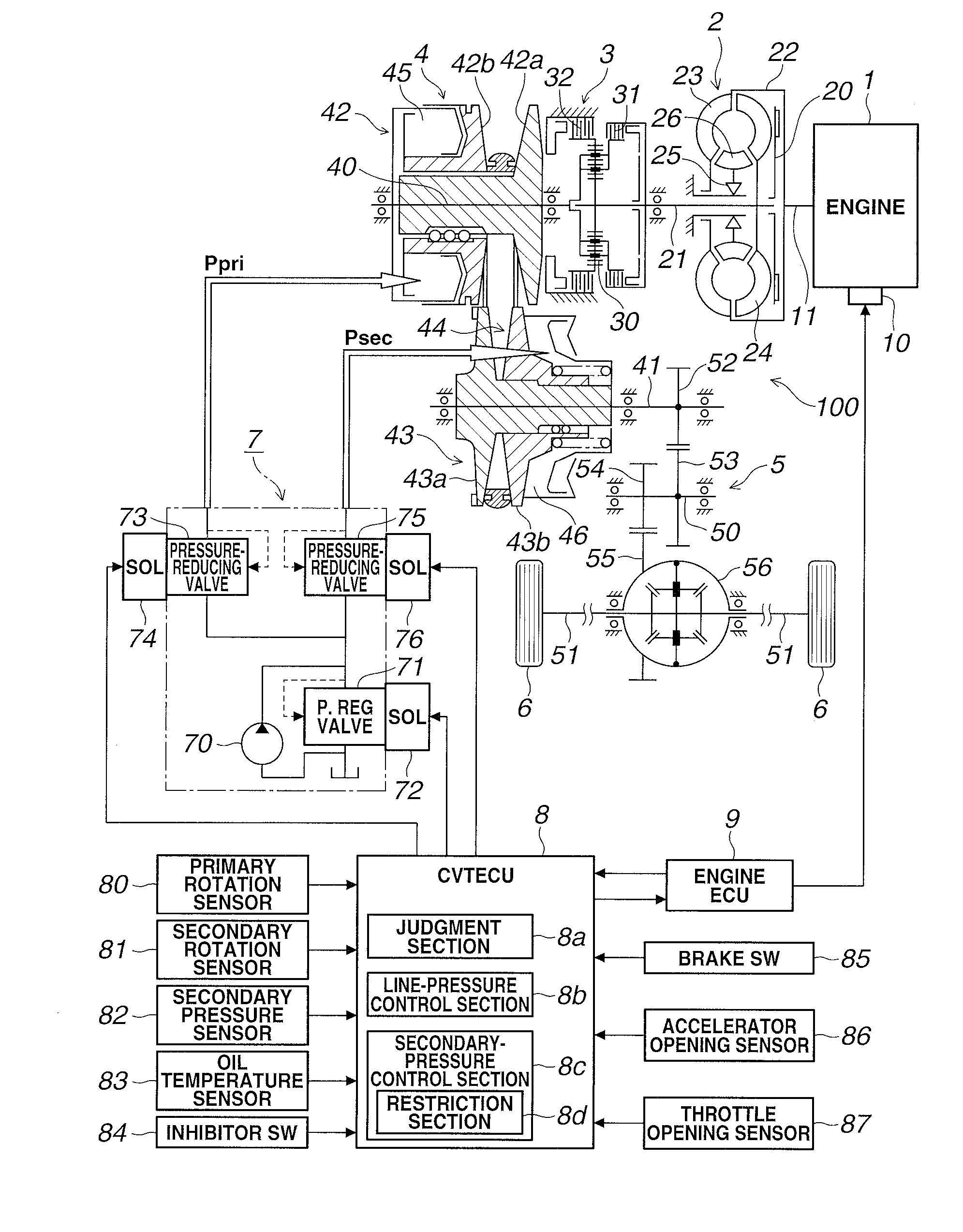
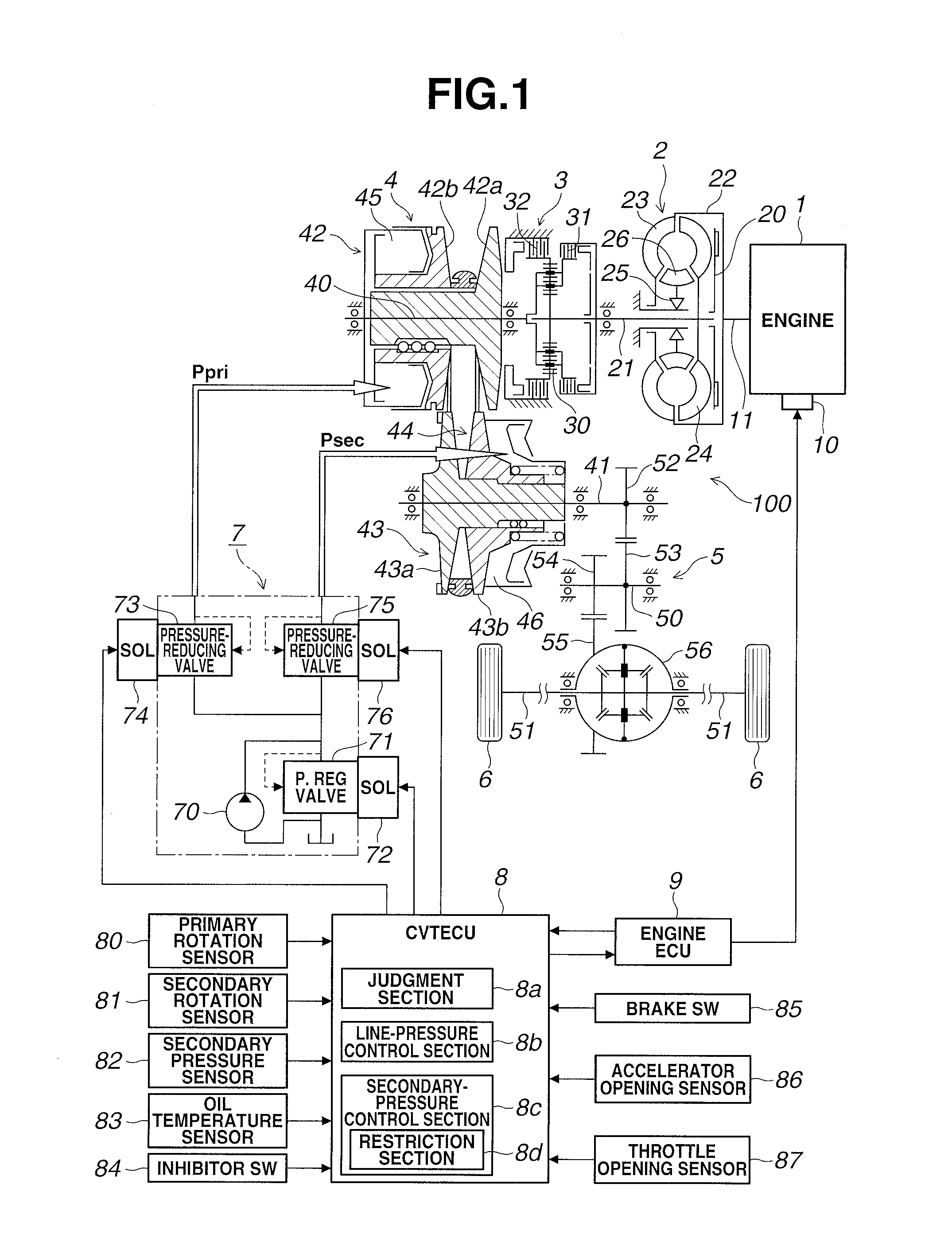
[0041]Hereinafter, referring to the drawings, embodiments according to the present invention will be explained. It is noted that the following embodiments are just examples, and hence, various modifications and technical applications which are not clearly described in the following embodiments are not excluded from the present invention. Respective configurations in the following embodiments can be used by variously modifying the respective configurations within those ideas. Moreover, some of the respective configurations can be selected or properly combined as needed.

[0042]Moreover, in after-mentioned hydraulic controls, a line pressure, a primary pressure and a secondary pressure are controlled. Actual values of the line pressure, the primary pressure and the secondary pressure will be respectively referred to as an actual line pressure, an actual primary pressure and an actual secondary pressure.

[0043]Among these actual pressures, the actual secondary pressure can be sensed by a ...


PUM


Abstract

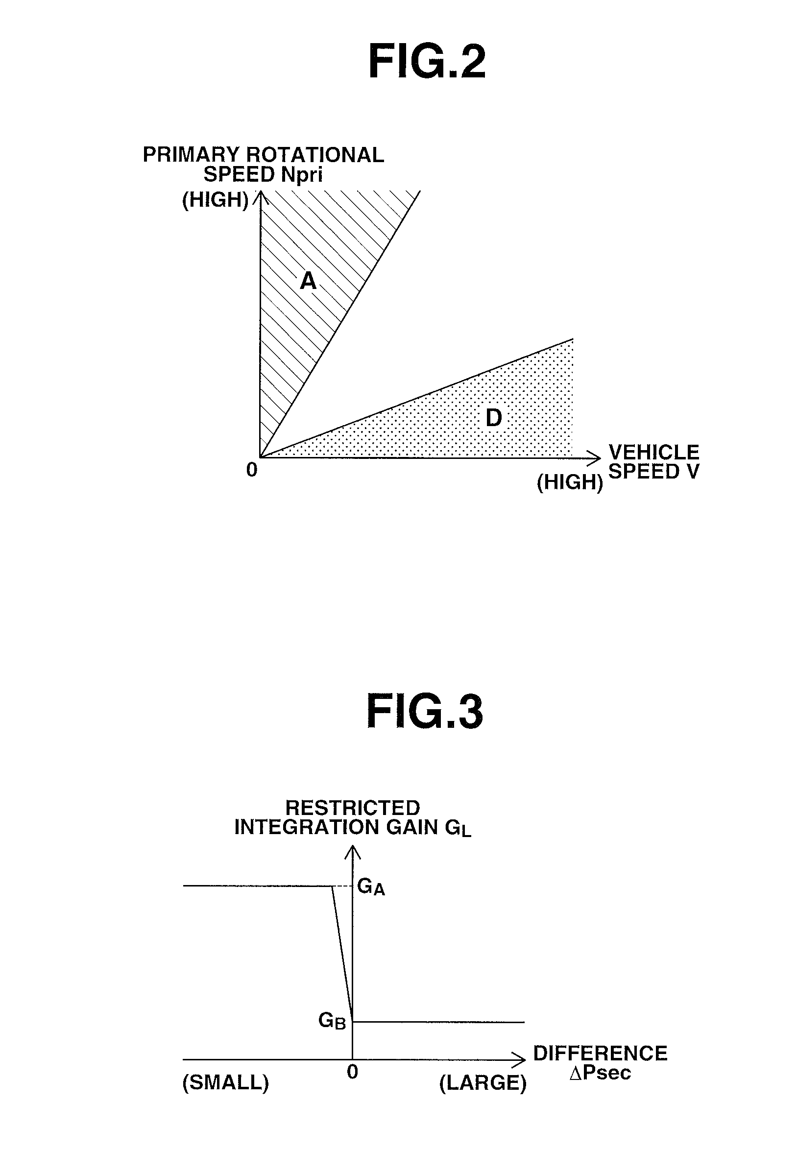
A CVTECU includes a secondary-pressure control section and a line-pressure control section that performs a same-pressure control to equalize a line pressure and a secondary pressure with each other if a predetermined start condition is satisfied. The line-pressure control section realizes a same-pressure state between the line pressure and the secondary pressure by lowering the line pressure below a target secondary pressure, and then controls the line pressure such that an actual secondary pressure is brought to the target secondary pressure by hydraulic feedback control while maintaining the same-pressure state. The secondary-pressure control section includes a restriction section that restricts an accumulation of integral term of an integral action for a duration between a time point at which the actual secondary pressure starts to be pushed down and a time point at which the same-pressure state between the line pressure and the secondary pressure is realized.

Description

TECHNICAL FIELD[0001]The present invention relates to a control device for a belt-type continuously variable transmission which continuously changes and outputs rotational speed of an engine, a motor or the like that is a drive source of a vehicle.BACKGROUND ART[0002]A belt-type continuously variable transmission (hereinafter referred to as “CVT”) is constituted by winding a belt around an input-side primary pulley and an output-side secondary pulley. Torque of the engine is inputted to the input-side primary pulley, and the output-side secondary pulley outputs torque to wheels. Each of the primary pulley and the secondary pulley includes a fixed pulley and a movable pulley which form a V-groove. Each of the movable pulleys is biased toward the fixed pulley by a primary pulley pressure (hereinafter referred to as “primary pressure”) or a secondary pulley pressure (hereinafter referred to as “secondary pressure”) which is produced by using a line pressure as a base pressure. Accordin...

Claims


Application Information

Patent Timeline
IPC IPC(8): F16H61/662F16H9/16
CPCF16H61/662F16H9/16F16H61/0021F16H61/66272
Inventor HONMA, TOMOAKITAKAHASHI, SEIICHIROKOBAYASHI, TAKAHIROEGUCHI, TAKASHINOBU, HISAOSAKAKIBARA, KENJI
Owner JATCO LTD
Learn More