
Turbine component thermal barrier coating with crack isolating engineered groove features

a technology of thermal barrier coating and engineered groove, which is applied in the direction of machines/engines, stators, mechanical equipment, etc., can solve the problems of tbc layer structural integrity, cracking of tbc layer as well as tbc/turbine component adhesion loss at the interface of dissimilar materials, and achieve the effect of enhancing tbc layer adhesion

Inactive Publication Date: 2016-12-15
SIEMENS AG
View PDF2 Cites 10 Cited by
  • Summary
  • Abstract
  • Description
  • Claims
  • Application Information

AI Technical Summary

Benefits of technology

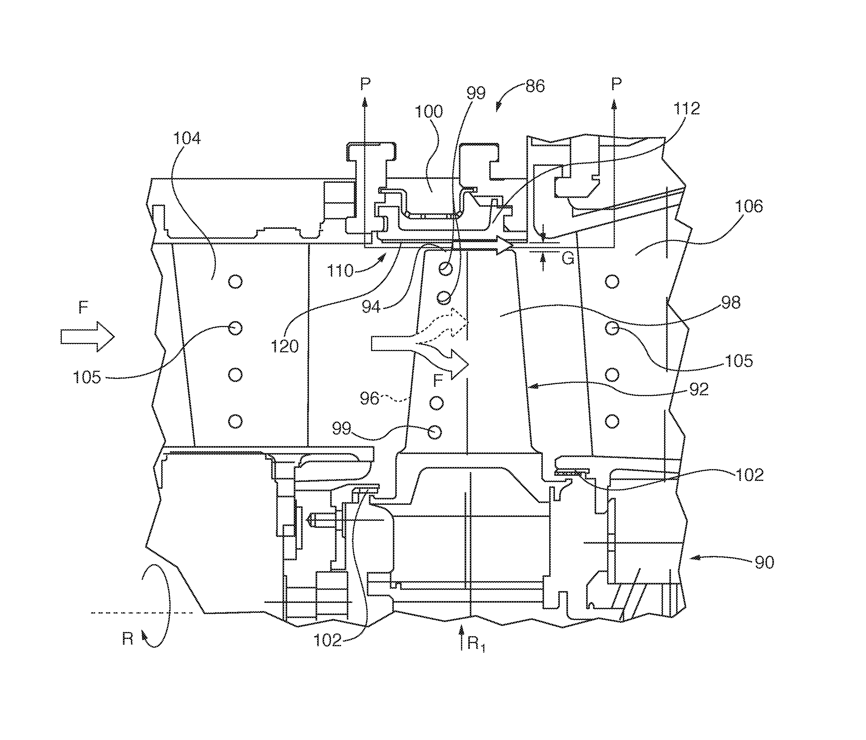
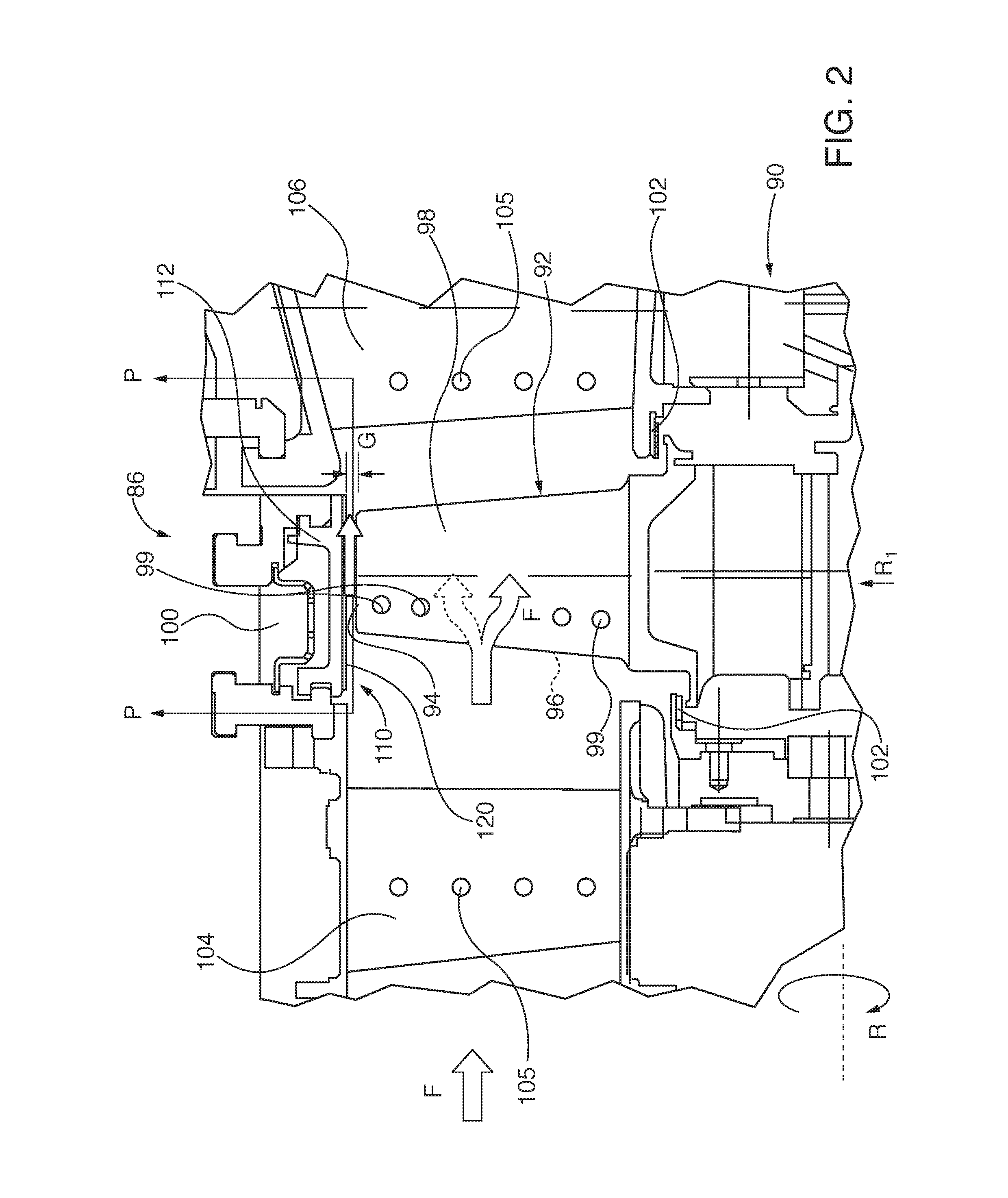
[0020]In some embodiments, spallation of cracked TBC material that is constrained within ESFs and / or EGFs leaves a partial underlying TBC layer that is analogous to a road pothole. The underlying TBC material that forms the floor or base of the “pot hole” provides continuing thermal protection for the turbine engine component underlying substrate.
[0023]CMAS containing combustion particulates to the TBC layer. When CMAS-retardant layers are applied over EGFs, they inhibit accumulation of foreign material within the grooves and provide smoother boundary layer surfaces to enhance combustion gas flow aerodynamic efficiency.

Problems solved by technology

Due to differences in thermal expansion, fracture toughness and elastic modulus—among other things—between typical metal-ceramic TBC materials and typical superalloy materials used to manufacture the aforementioned exemplary turbine components, there is potential risk of cracking the TBC layer as well as TBC / turbine component adhesion loss at the interface of the dissimilar materials.
The cracks and / or adhesion loss / delamination negatively affect the TBC layer structural integrity and potentially lead to its spallation, i.e., separation of the insulative material from the turbine component.
Such cracking loss of TBC structural integrity can lead to further, premature damage to the underlying component substrate.
During continued operation of the turbine engine, it is possible over time that the hot combustion gasses will erode or otherwise damage the exposed component substrate surface, potentially reducing engine operation service life.
Potential spallation risk increases with successive powering on / off cycles as the engine is brought on line to generate electrical power in response to electric grid increased load demands and idling down as grid load demand decreases.
In addition to thermal or vibration stress crack susceptibility, the TBC layer on engine components is also susceptible to foreign object damage (FOD) as contaminant particles within the hot combustion gasses strike the relatively brittle TBC material.
A foreign object impact can crack the TBC surface, ultimately causing spallation loss of surface integrity that is analogous to a road pothole.
Once foreign object impact spalls of a portion of the TBC layer, the remaining TBC material is susceptible to structural crack propagation and / or further spalling of the insulative layer.
In addition to environmental damage of the TBC layer by foreign objects, contaminants in the combustion gasses, such as calcium, magnesium, aluminum, and silicon (often referred to as “CMAS”) can adhere to or react with the TBC layer, increasing the probability of TBC spallation and exposing the underlying bond coat.
Past attempts to enhance TBC layer structural integrity and affixation to underlying turbine component substrates have included development of stronger TBC materials better able to resist thermal cracking or FOD, but with tradeoffs in reduced thermal resistivity or increased material cost.

Method used


Image

  • Turbine component thermal barrier coating with crack isolating engineered groove features
  • Turbine component thermal barrier coating with crack isolating engineered groove features
  • Turbine component thermal barrier coating with crack isolating engineered groove features

Examples


embodiment 272

[0102]Dimensions of an exemplary chevron-shaped MSF 272 are shown in FIG. 10. The chevron-shaped MSFs 272, having closed continuous leading edges 273, trailing edges 274, top surfaces 275 facing the rotating turbine blades. Staggered rows of chevrons 272 create a tortuous path for hot gas flow. Each chevron shaped MSF embodiment 272 has width W, length L and Height H dimensions that occupy a volume envelope of 1-12 cubic millimeters. In some embodiments, the ratio of MSF length and gap defined between each MSF is approximately in the range of 1:1 to 1:3. In other embodiments, the ratio of MSF width and gap is approximately 1:3 to 1:8. In some embodiments, the ratio of MSF height to width is approximately 0.5 to 1.0. Feature dimensions can be (but not limited to) between 3 mm and 10 mm, with a wall height and / or wall thickness of between 100-2000 microns (μm).

[0103]As with the blade tip abradable components embodiments shown in FIGS. 3-8, MSF heights can be varied within the PMPP for...

embodiment 470

[0122]In FIG. 38 the turbine component 440 has an EGF 442 that circumscribes a plurality of cooling holes 99 / 105, which is analogous to a ditch or moat surrounding the hole cluster. Propagation of any surface delamination within the cluster of cooling holes 99 / 105 surrounded by the EGF 442 is confined within the EGF 442. In the embodiments of FIGS. 39-41, the EGFs do not fully surround any one cooling hole, but delamination spread is likely to be arrested by one or more partially circumscribing EGSs near one or more of the holes. In FIG. 39, one or more of horizontally oriented EGFs 452 or vertically oriented EGFs 454 in the turbine component 450 TBC outer layer surface partially or fully surrounds each of the cooling holes 99 / 105. In FIG. 40, the turbine component 460 cooling holes 99 / 105 are circumscribed, fully or partially, by the undulating ribbon-like EGFs 462 or 464. In the turbine component embodiment 470 of FIG. 41 a combination of linear EGFs 474 and semi-circular or arcua...

embodiment 560

[0130]In FIG. 48, the turbine component embodiment 560 has a curved surface substrate 561, such as on the leading edge of a turbine blade or vane. A bond coat BC 562 is applied to the substrate and includes a three-dimensional planform array of waffle pattern-like ESFs 564 that define wells or holes for anchoring of a bi-layer thermal barrier coat 566. The TBC 566 includes a lower thermal barrier coat (LTBC) 567 and an outer thermal barrier coat (OTBC) 568. EGFs 569 are cut into the outer surface of the OTBC 568 in a waffle-like three-dimensional planform array that does not necessarily have to be aligned concentrically with the ESF 564 array pattern within the TBC layer 566. If so aligned, each bi-layer three-dimensional segment that is captured in the similar groove formed within the ESFs 564 is analogous to a kernel or corn or maize that is embedded within its cob.

[0131]The turbine component embodiment 570 of FIG. 49 adds a CMAS-resistant layer 580 to the surface of the OTBC laye...


PUM

PropertyMeasurementUnit
combustion temperaturesaaaaaaaaaa
thicknessaaaaaaaaaa
thicknessaaaaaaaaaa

Abstract

Engineered groove features (EGFs) are formed within thermal barrier coatings (TBCs) of turbine engine components. The EGFs are advantageously aligned with likely stress zones within the TBC or randomly aligned in a convenient two-dimensional or polygonal planform pattern on the TBC surface and into the TBC layer. The EGFs localize thermal stress- or foreign object damage (FOD)-induced crack propagation within the TBC that might otherwise allow excessive TBC spallation and subsequent thermal exposure damage to the turbine component underlying substrate. Propagation of a crack is arrested when it reaches an EGF, so that it does not cross over the groove to otherwise undamaged zones of the TBC layer. In some embodiments, the EGFs are combined with engineered surface features (ESFs) that are formed in the component substrate or within intermediate layers applied between the substrate and the TBC.

Description

PRIORITY CLAIM AND CROSS-REFERENCE TO RELATED APPLICATIONS[0001]This application claims priority under the following U.S. Patent Applications, the entire contents of each of which is incorporated by reference herein:[0002]“TURBINE ABRADABLE LAYER WITH PROGRESSIVE WEAR ZONE HAVING A FRANGIBLE OR PIXELATED NIB SURFACE”, filed Feb. 25, 2014, and assigned U.S. Ser. No. 14 / 188,941; and[0003]“TURBINE ABRADABLE LAYER WITH PROGRESSIVE WEAR ZONE MULTI LEVEL RIDGE ARRAYS”, filed Feb. 25, 2014, and assigned U.S. Ser. No. 14 / 188,958.[0004]A concurrently filed International Patent Application entitled “TURBINE ABRADABLE LAYER WITH AIRFLOW DIRECTING PIXELATED SURFACE FEATURE PATTERNS”, docket number 2013P20413WO, and assigned serial number (unknown) is identified as a related application and is incorporated by reference herein.[0005]The following United States Patent Applications are identified as related applications for purposes of examining the presently filed application, the entire contents ...

Claims


Application Information

Patent Timeline
Patent Type & Authority Applications(United States)
IPC IPC(8): F01D5/28C23C4/12C23C4/04F01D5/18F01D9/02
CPCF01D5/288F05D2260/941F01D9/02C23C4/04C23C4/12F05D2220/32F05D2230/311F05D2230/312F05D2230/90F05D2250/18F05D2250/28F05D2250/294F05D2300/5023F05D2300/10F05D2300/21F05D2300/516F01D5/18F01D11/122F01D5/187F01D9/041F01D11/08F01D25/12F05D2220/31F05D2240/11F05D2250/00F05D2250/141F05D2250/181F05D2250/182F05D2250/185F05D2250/23F05D2260/202F05D2260/231F05D2300/611
Inventor SUBRAMANIAN, RAMESHHITCHMAN, NEILZOIS, DIMITRIOSSHIPPER, JR., JONATHAN E.SCHILLIG, CORA
Owner SIEMENS AG
Learn More