Support for attaching a portable device to a vehicle rear-view mirror

a technology for portable devices and rearview mirrors, which is applied in the direction of electrical devices, optical viewing, electric vehicles, etc., can solve the problems of not being easy to standardize, the jaws do not clamp in a stable way, and the unstuckness of the jaws, etc., to achieve the effect of simple servi

Inactive Publication Date: 2016-12-15
JODON DE VILLEROCHE GERARD
View PDF3 Cites 9 Cited by
  • Summary
  • Abstract
  • Description
  • Claims
  • Application Information

AI Technical Summary

Benefits of technology

[0014]In the second embodiment especially, the clamp serves not to get hooked to the ball joint pin of the rear-view mirror which it circumvents, but as a hook on the upper rim of the rear-view mirror; thus, it has an L-shaped angle in its upper part and has a hook at the top of the rear-view mirror facing the lower support or cap to cooperate with the lower edge of the rear-view mirror. The invention provides for several dimensions of U-shaped clamps in their part acting as hooks on the edge of the rear-view mirror so as to adapt to any rear-view mirror. This embodiment has the advantage of being simple to serve a set of rear-view mirrors provided that there are several small arms of different dimensions with hooks to adapt to this set of rear-view mirrors.
[0015]In the third embodiment especially, the hooking element is formed by a set of two distinct L-shaped hooks, the greater leg of which forms said slide cooperating with the guideways or wells, the shortest leg of which faces the bottom support to cooperate with the upper edge of the rear-view mirror. This embodiment has the advantage of adapting to all the existing rear-view mirrors inasmuch as a set has rectangular several hooks, the small horizontal hooked arm which varies according to the thickness of the rear-view mirror. The feet of the large legs are provided with spikes so that the staple that clamps them in the well immobilizes them by stress.
[0016]In the fourth embodiment especially, the hooking element is formed by a set of two similar L-shaped hooks, the greatest leg of which forms said slide cooperating with the guideways or wells, and the length of which, both for the horizontal part on the top of the rear-view mirror and the vertical part on the back of the rear-view mirror, is constituted by successive hinged links, linking them to one another, like the generally metallic watch straps available in the market, except that while the present invention of the support for the attachment of a portable device to a vehicle rear-view mirror is made of plastic, these links are also made of plastic, with a coefficient of solidity that is possibly different, these links being connected together made by horizontal pins threaded into lateral hinge knuckles and in the middle of each of the links or alternatively by pegs in front of the links and holes behind the links, the first links being shaped like hooks on the upper rim of the rear-view mirror, a certain number of links forming the small side of L shape of the hook horizontally against the upper edge of the rear-view mirror, a certain number of links, one or two in general, forming the turning point of the angle formed by the horizontal and vertical sides of the rear-view mirror, the other links descending vertically along the rear of the rear-view mirror to terminate in the last link in being connected by a horizontal pin to the vertical part of a leg or in another way for example by a hook or a screw or pegs at the top of the legs, similarly to the legs described here above, in proportion to the perimeter on the upper horizontal side of the rear-view mirror, plus the vertical side of the rear-view mirror, this leg entering into the wells or guideways constituted in the first means, perpendicular to the support. The advantage of this embodiment is that the unit constituted by the links, the number of which is variable according to the assembly, very exactly matches the horizontal shape of the top rear-view mirror, its rounded form towards the rear side of the rear-view mirror and the rear, often domed shape of the rear-view mirror. The principle of tightening the legs of the hooks with links entering the wells is exactly the same, i.e. it is done by a tightening of the screws of the staple, stressing the ends of the staple against the spikes of these legs. The mobility of the links relative to one another and their number makes it possible to adapt to any shape of rear-view mirror. Preference is given to links of dimensions similar to those of watch straps. The links of the invention are made of plastic or metal. They could be made of rubber. The present patent application extends the concept of this second aspect by replacing the set of links with a single element consisting of a rubber band starting from the hook before the rear-view mirror up to the well. The links can be connected by different types of dowels such as conical dowels, elastic dowels, safety splints, helicoidally threaded dowels, etc.

Problems solved by technology

In the former case, they have the drawback of getting unstuck whenever there is a change of humidity or temperature in the vehicle.
The method of hooking these devices to the air vents has the drawback of not being easy to standardize.
The drawback of this device, which has parallel jaws, is that the rear-view mirror can have non-parallel lower and upper edges, or domed edges, so much so that the jaws do not clamp in a stable way.
Another drawback is that these jaws can clamp only on to the left-hand or right-hand side of the rear-view mirror and not in its middle so much so that the “shower hose” has to be oriented in order to act as a counterweight and any action applied manually to the mobile unit or to the GPS etc. causes imbalance to the rear-view mirror through the gripping of the jaws on the side.
The mobile phone or the GPS device fixed to the extremity of the “shower hose” has another drawback of being anchored relatively solidly so much so that in the event of impact, this “shower hose” resists the impact and can cause injury.

Method used


Image

  • Support for attaching a portable device to a vehicle rear-view mirror
  • Support for attaching a portable device to a vehicle rear-view mirror
  • Support for attaching a portable device to a vehicle rear-view mirror

Examples


Embodiment Construction

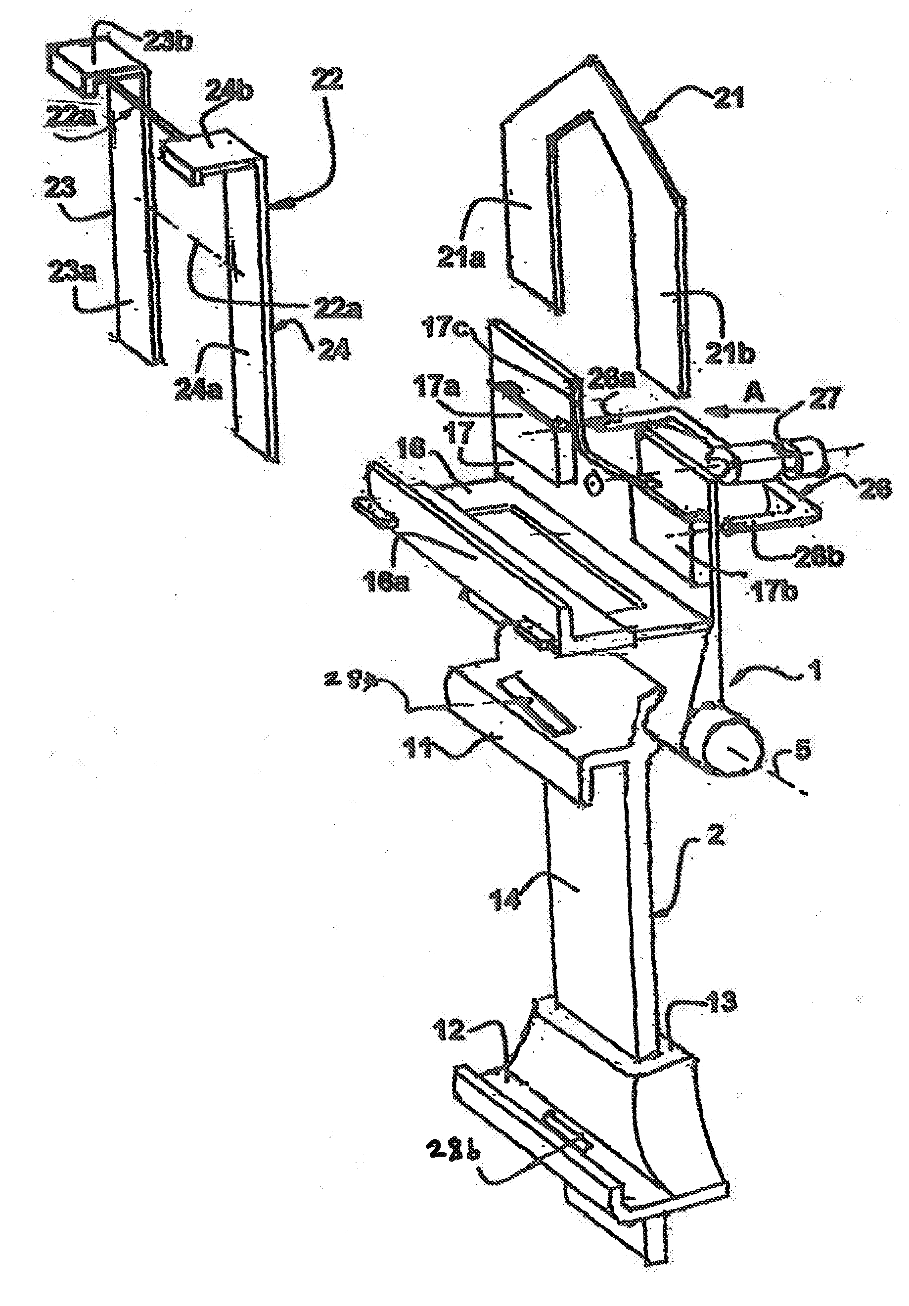
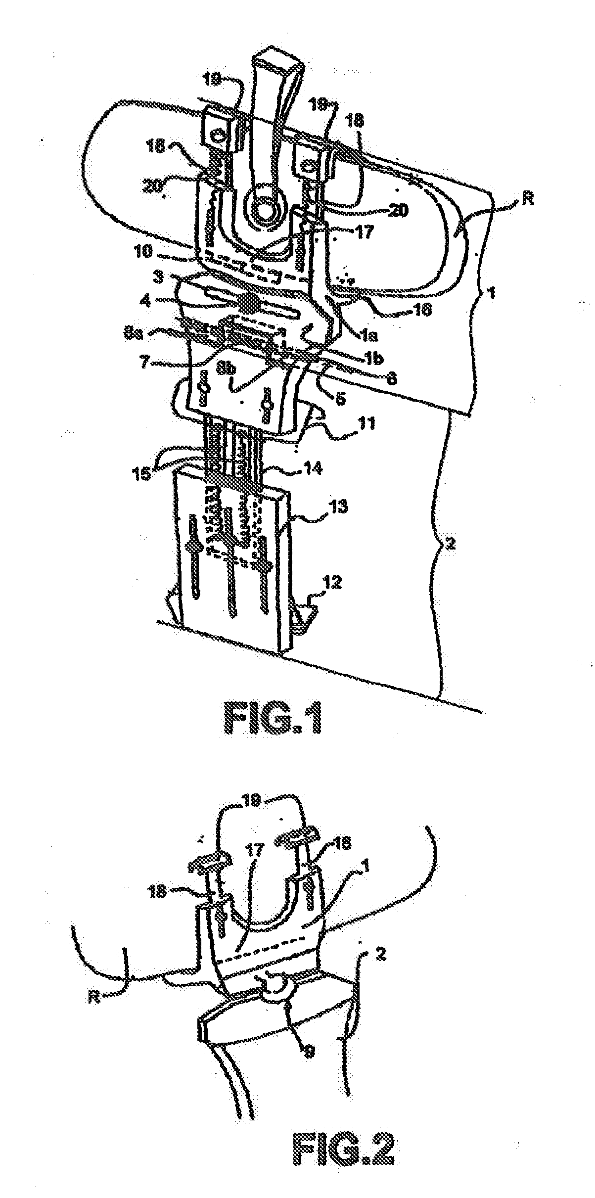
[0033]In FIG. 1, the support according to the invention is constituted by two parts.

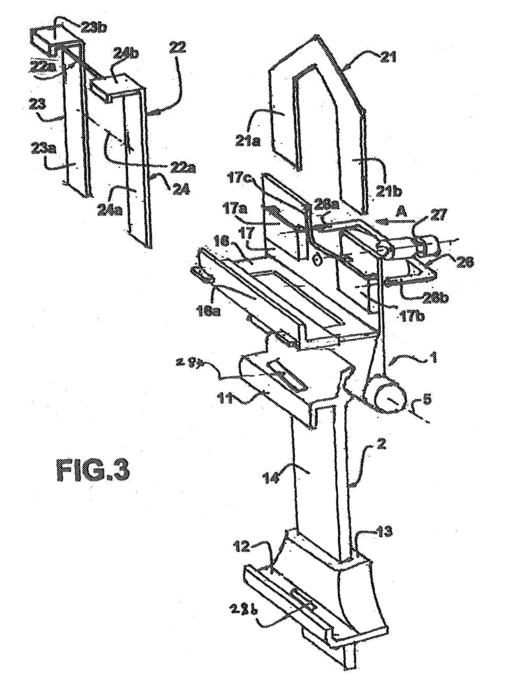
[0034]The first part (1) comprises means to get fixed to the rear-view mirror (R) of the vehicle. These, means will be explained in greater detail with reference to FIG. 3.

[0035]The second part (2) comprises means to receive and maintain an apparatus such as a portable telephone or a navigation assistance device known as a GPS, each provided with a screen, in a known way, or the generally electronic or electrical devices listed here above, means which will be explained in greater detail with reference to FIGS. 1, 3, 5, 6, 7 and 8.

[0036]The two parts (1) and (2) can be indexed relative to each other around a substantially vertical axis when the support is fixed to the rear-view mirror. The means providing for this indexing are for example an oblong aperture (3) made in the element (1) crossed by a screw (4) implanted in the element (1). One of the elements (1) and (2) rests on the other by means of a ...


PUM


Abstract

A support is provided for attachment to an internal rear-view mirror made from plastic material or lightweight metal for a portable device having a telephone or GPS display screen or for generally electronic, electrical or other devices. The support includes a hooking member shaped to engage with another part of the rear-view mirror, the upper edge thereof, via two hooks, located to either side of a ball pin attaching the rear-view mirror to the windscreen. The hooking member is formed in part from a plurality of links articulated by hinges, in the manner of a metal watch strap. The hooking member is started by a hook-shaped link that secures to the upper edge of the rear-view mirror, followed by a series of links, varying in number, so as to match and constrain the shape of the rear-view mirror, and is finished by two leg feet that form a slide.

Description

CROSS-REFERENCE TO RELATED APPLICATIONS[0001]This Application is a Section 371 National Stage Application of International Application No. PCT / EP2014 / 072992, filed Oct. 27, 2014, the content of which is incorporated herein by reference in its entirety, and published as WO 2015 / 082132 A1 on Jun. 11, 2015, not in English.FIELD OF THE DISCLOSURE[0002]The present invention relates to a support for attaching a portable communications device or positioning device to the inside rear-view mirror of a vehicle, this portable device being provided with a display screen and operating commands, for example a cell-phone called a portable phone or a device providing assistance in the driving of a vehicle, called a GPS, and generally electrical or electronic devices, listed here below, that can be used by the driver.BACKGROUND OF THE DISCLOSURE[0003]There are fixtures for attaching such devices (called “portable” devices, mobile telephones or GPS devices) to the windshield or to the instrument pane...

Claims


Application Information

Patent Timeline
Patent Type & Authority Applications(United States)
IPC IPC(8): B60R11/02B60R1/04H02J50/10H02J7/02H02J7/35
CPCB60R11/0241B60R11/0258H02J7/025H02J7/355B60R2011/0089B60R1/04B60R2011/0033B60R2011/0059B60R2011/0071H02J50/10B60R2011/0294H02J7/35
Inventor JODON DE VILLEROCHE, GERARD
Owner JODON DE VILLEROCHE GERARD
Why Eureka
Try Eureka