Drive device for belt conveyor device

Active Publication Date: 2016-12-01
SANKI ENG CO LTD
View PDF7 Cites 9 Cited by
  • Summary
  • Abstract
  • Description
  • Claims
  • Application Information

AI Technical Summary

Benefits of technology

The present invention aims to reduce the cost and manufacturing costs of parts, prevent product meandering, address torsional moments applied to the drive shaft, and improve the positioning of the drive motor. Other technical effects include reducing the moment applied to the drive shaft, reducing force absorbed by the drive shaft, and enabling transparent visibility of the contact surface between the rear surface of the belt and the drive pulley. Additionally, the invention avoids the need for a side frame made of metal material and facilitates maintenance.

Problems solved by technology

Therefore, these become causes of increasing product costs of respective parts which form the drive device as above, and manufacturing costs at the time of assembling the drive device.
Therefore, when manufacturing a belt conveyor device for light conveyance object in which there are plural demands regarding the width of endless belt, it is required to manufacture parts which form a drive device in accordance with a width dimension of the endless belt, so that the number of parts to be prepared as a product series is further increased, which leads to increase in the product costs and the manufacturing costs.

Method used


Image

  • Drive device for belt conveyor device
  • Drive device for belt conveyor device
  • Drive device for belt conveyor device

Examples


Embodiment Construction

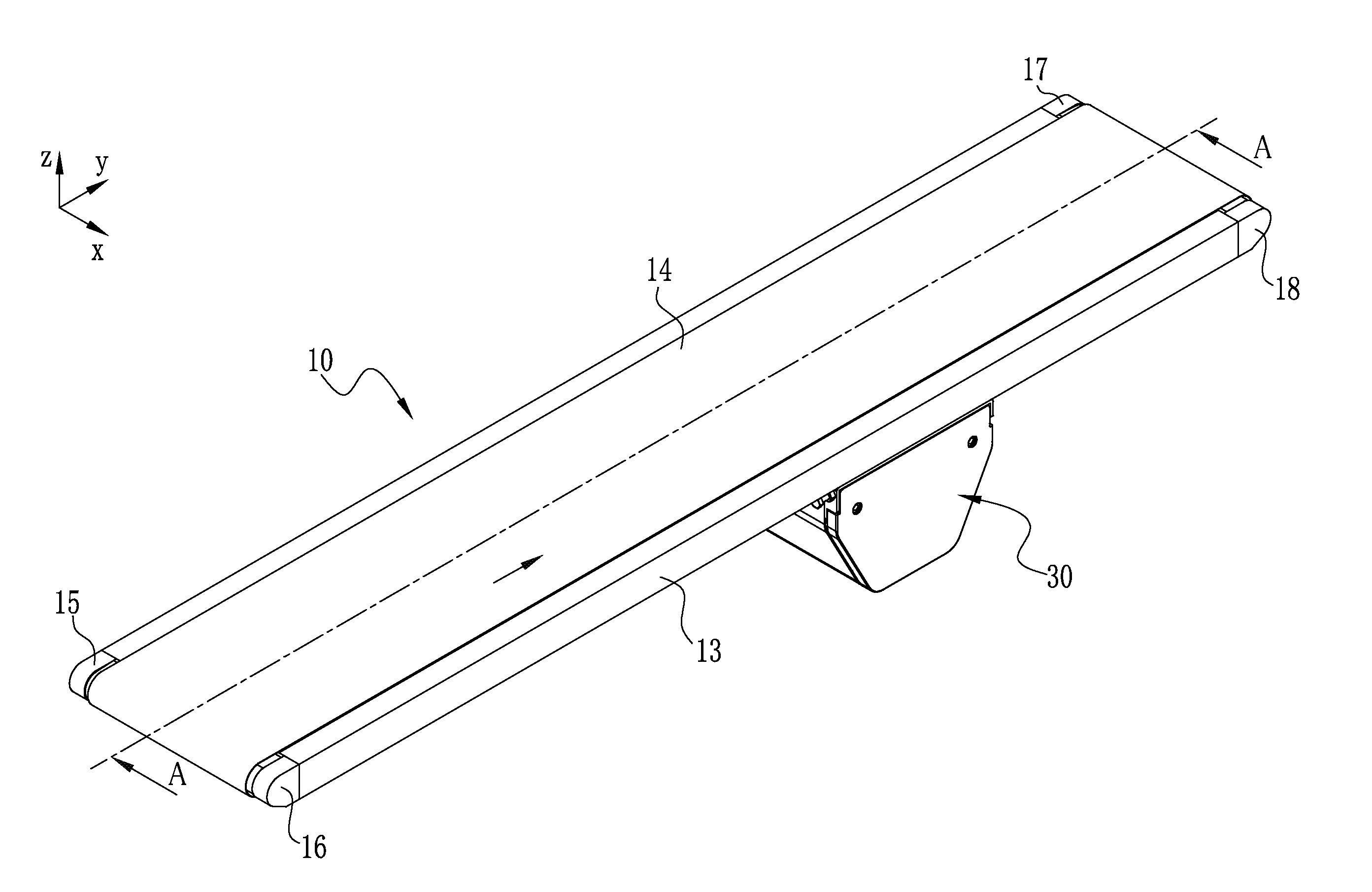
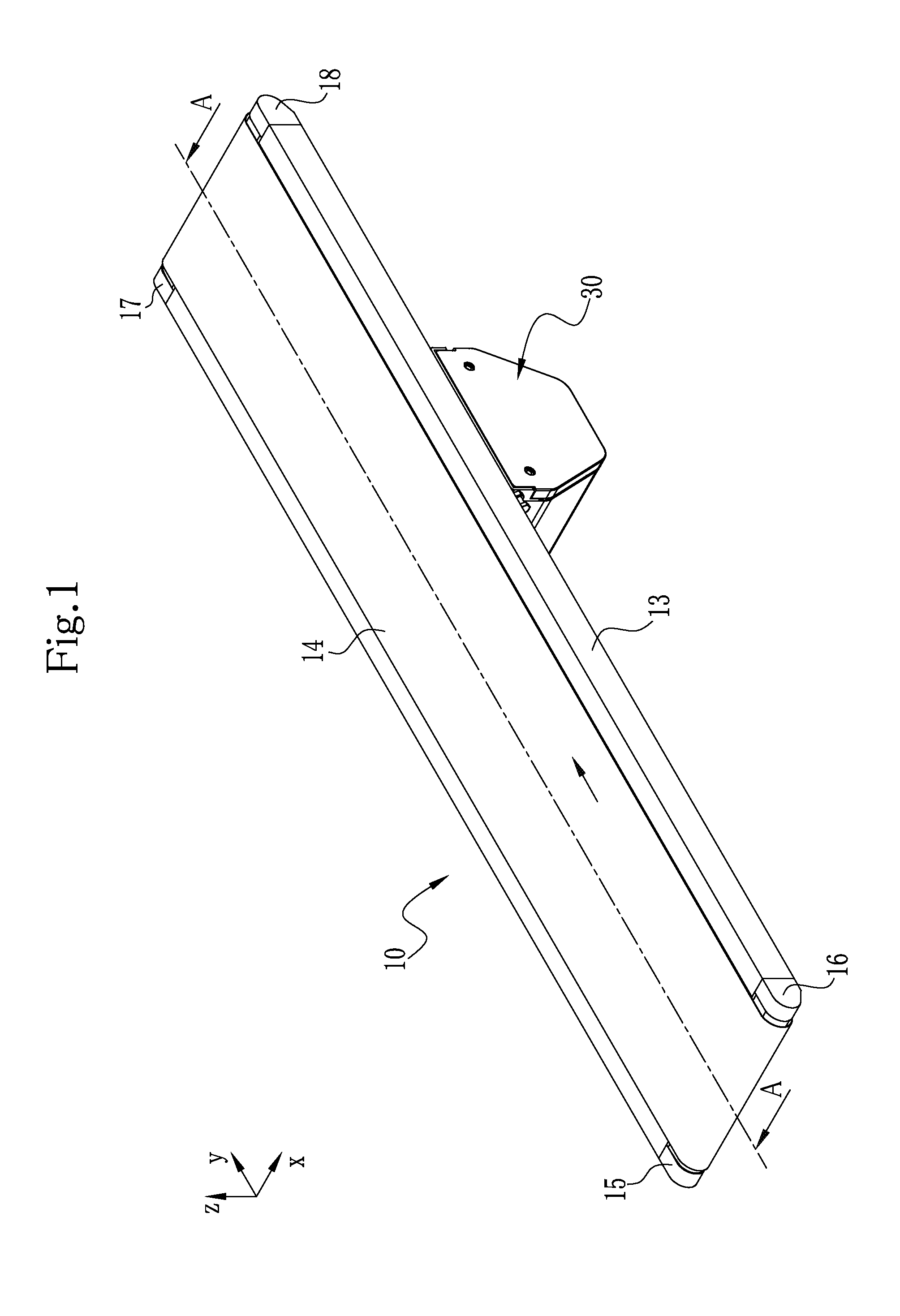
[0039]Hereinafter, a belt conveyor device provided with a drive device of the present invention will be described. A belt conveyor device 10 illustrated in FIG. 1 to FIG. 3 is a belt conveyor device which conveys a lightweight conveyance object (conveyance object whose weight is up to about 10 kg) such as food products, medical products, cosmetics, and automotive parts. In this belt conveyor device, plural specifications regarding an endless belt to be used are set. Note that as the specification of the endless belt 14, there can be cited a belt width of the endless belt 14.

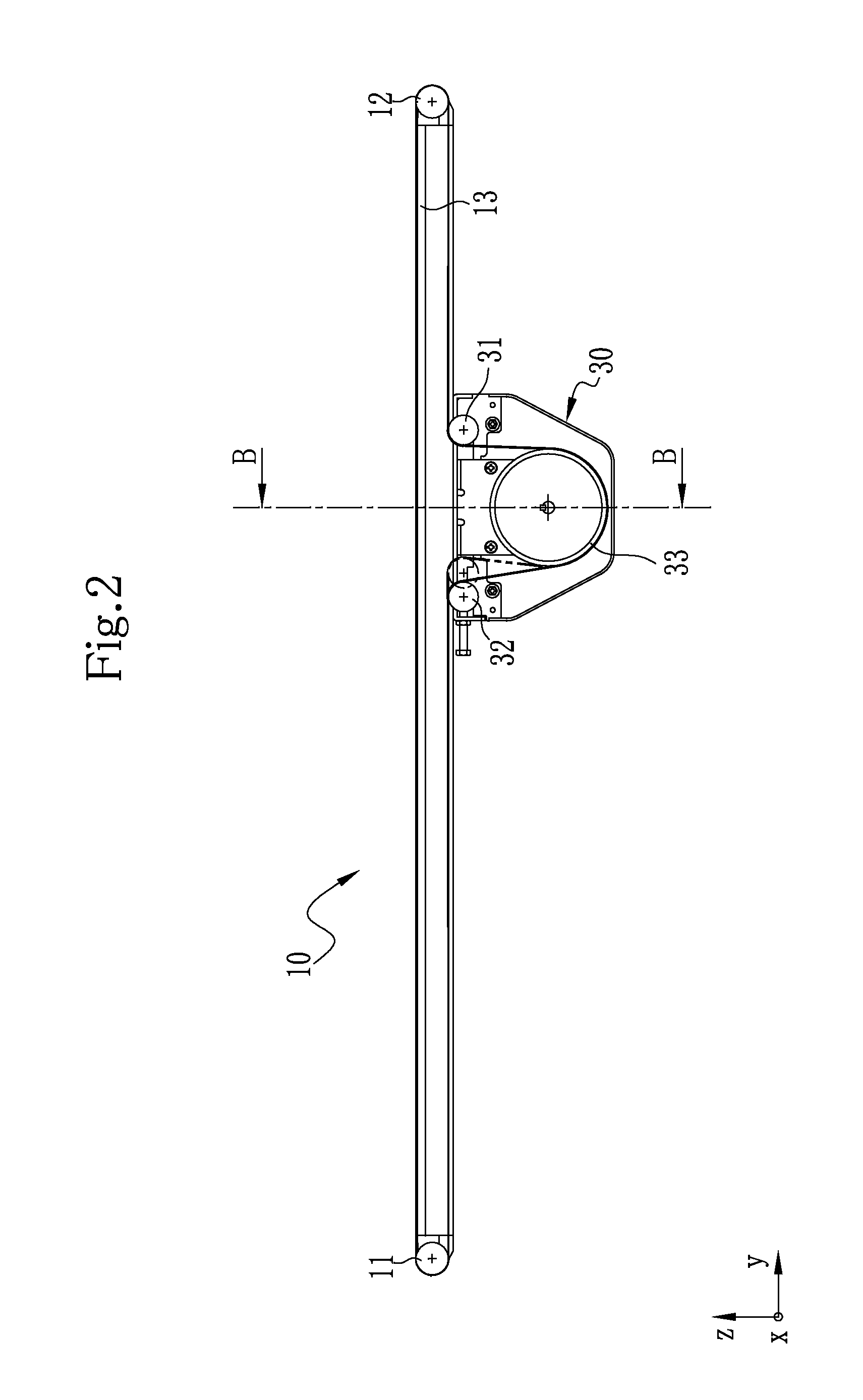
[0040]The belt conveyor device 10 includes two pulleys 11, 12, a conveyor frame 13, the endless belt 14, and a drive device 30. Hereinafter, out of the two pulleys 11, 12, the pulley 11 disposed on an upstream side in a conveyance direction of a conveyance object (y direction in FIG. 1) is referred to as a tail pulley 11, and the pulley 12 disposed on a downstream side in the conveyance direction is referred to a...


PUM


Abstract

A drive device for a belt conveyor device includes a drive pulley, a first pulley, a second pulley, a support frame, and a drive motor. The drive pulley has a drive shaft direction length less than a plurality of previously set belt widths of the endless belt and has the driving shaft direction length being set to a same length regardless of the plurality of previously set belt widths of the endless belt. Axial lengths of the first pulley and the second pulley are set to the same length as the axial lengths of the head pulley and the tail pulley. The support frame is rotatably attached to the first pulley and the second pulley. The drive motor hung from a lower surface of the support frame in order for the drive pulley to be positioned at an approximately center portion in a width direction of the endless belt.

Description

CROSS-REFERENCE TO RELATED APPLICATION[0001]This application is a U.S. National Stage application claiming the benefit of prior filed International Application Number PCT / JP2014 / 003722, filed Jul. 14, 2014, in which the International Application claims priority from Japanese Patent Application Number 2014-025442, filed on Feb. 13, 2014, the entire contents of which are incorporated herein by reference.TECHNICAL FIELD[0002]The present invention relates to a drive device for a belt conveyor device which conveys a conveyance object.BACKGROUND ART[0003]Recently, in our country, it has been shifted from heavy industry to light industry in which specialty products are manufactured and dealt. The number of situations where food products, medical products, cosmetics, automotive parts and the like are dealt is increasing, and needs for conveyance of lightweight objects in which the above products are dealt between processes or in distribution are on the rise.[0004]Needs of various users such...

Claims


Application Information

Patent Timeline
IPC IPC(8): B65G23/12B65G23/10B65G15/00
CPCB65G23/12B65G23/10B65G15/00B65G23/44
Inventor YAMAJI, YOSHITERU
Owner SANKI ENG CO LTD
Why Eureka
Try Eureka