
Imaging device for x-ray image

Active Publication Date: 2016-11-24
VA TECHNOLOGIE +1
View PDF6 Cites 0 Cited by
  • Summary
  • Abstract
  • Description
  • Claims
  • Application Information

AI Technical Summary

Benefits of technology

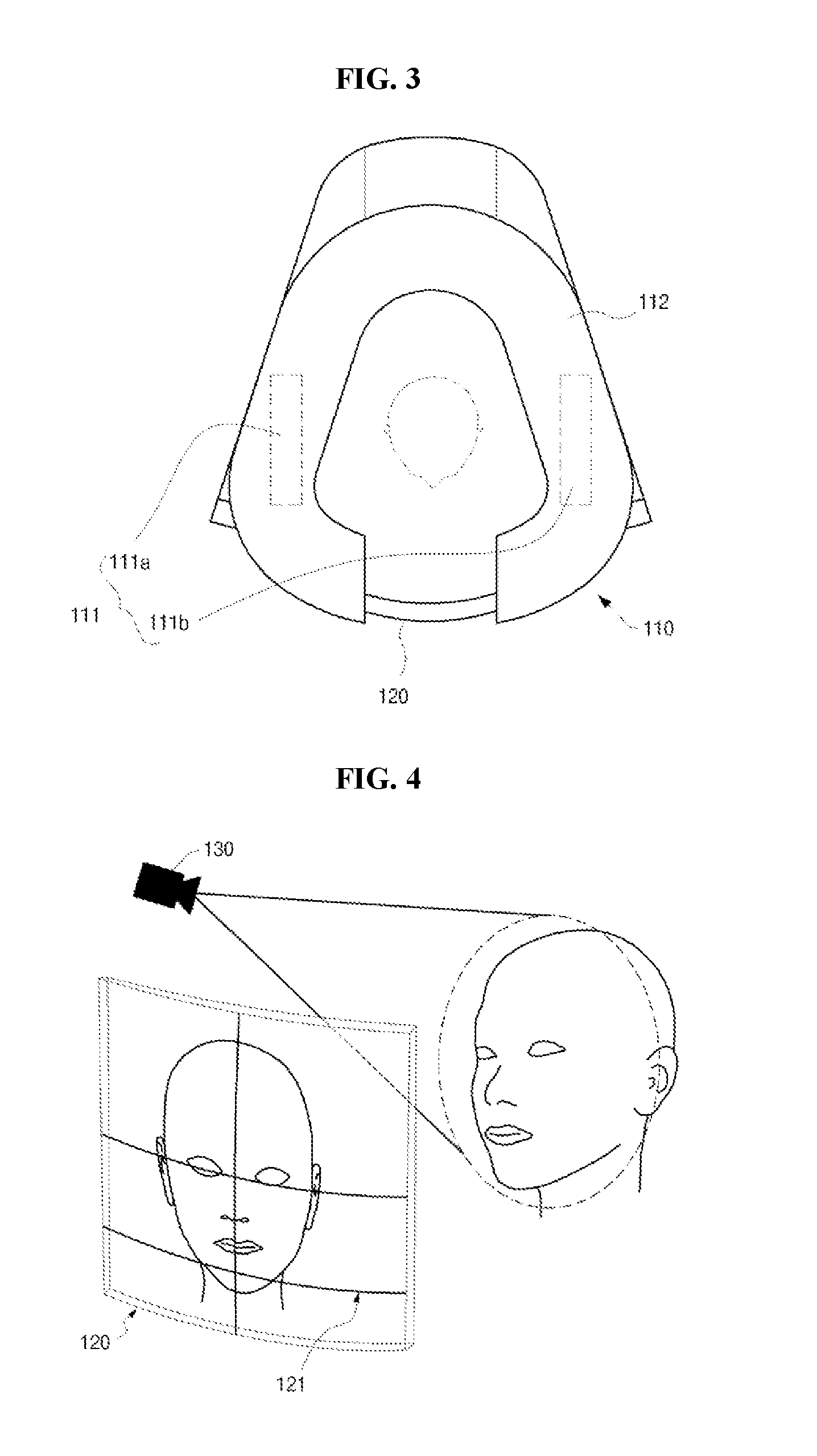
This patent describes a radiography machine that has a transparent subject check unit, which allows an operator to observe the patient and reduce their anxiety. A guide line is displayed on the check unit to prevent exposing the patient to the laser beam. The use of a touch panel on the check unit allows the operator to identify the subject and control the preferred settings for the radiography. Overall, this invention improves the patient experience and makes the image acquisition process easier for the operator.

Problems solved by technology

Furthermore, a radiography machine for radiographing the oral cavity and teeth of a patient may block the view of a patient or the view of an operator in some cases.
Thus, it is difficult for the operator to exactly correct the posture of the patient, thereby increasing the psychological anxiety of the patient.
When the posture of the patient does not reach a reference point of laser beam, an accurate radiograph cannot be obtained.

Method used


Image

  • Imaging device for x-ray image
  • Imaging device for x-ray image
  • Imaging device for x-ray image

Examples


Embodiment Construction

[0030]The terms used in this specification were selected as general terms which are widely used. However, the terms may include terms which were arbitrarily selected by the present applicant in specific cases. In this case, the meanings of the terms should be not simply understood through the terms, but understood in consideration of meanings described or used in the detailed descriptions of the present invention.

[0031]Hereafter, exemplary embodiments of the present invention will be described in detail with reference to the accompanying drawings.

[0032]However, the present invention is not limited to the exemplary embodiments, but may be embodied into another form. Throughout the specification, like reference numerals represent the same elements.

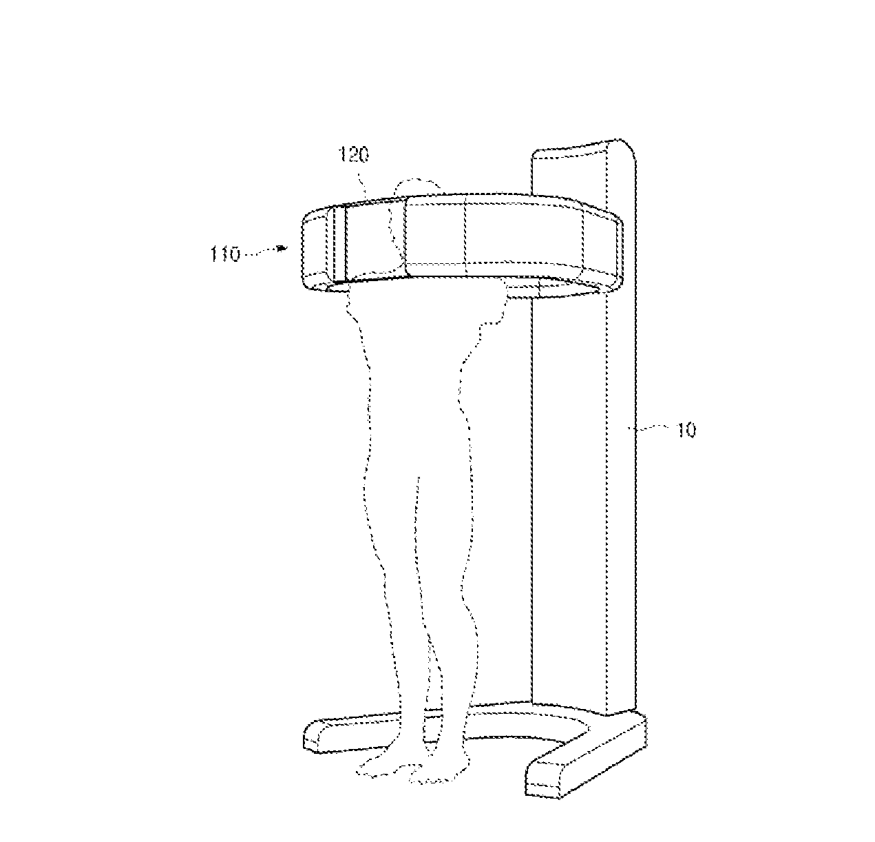
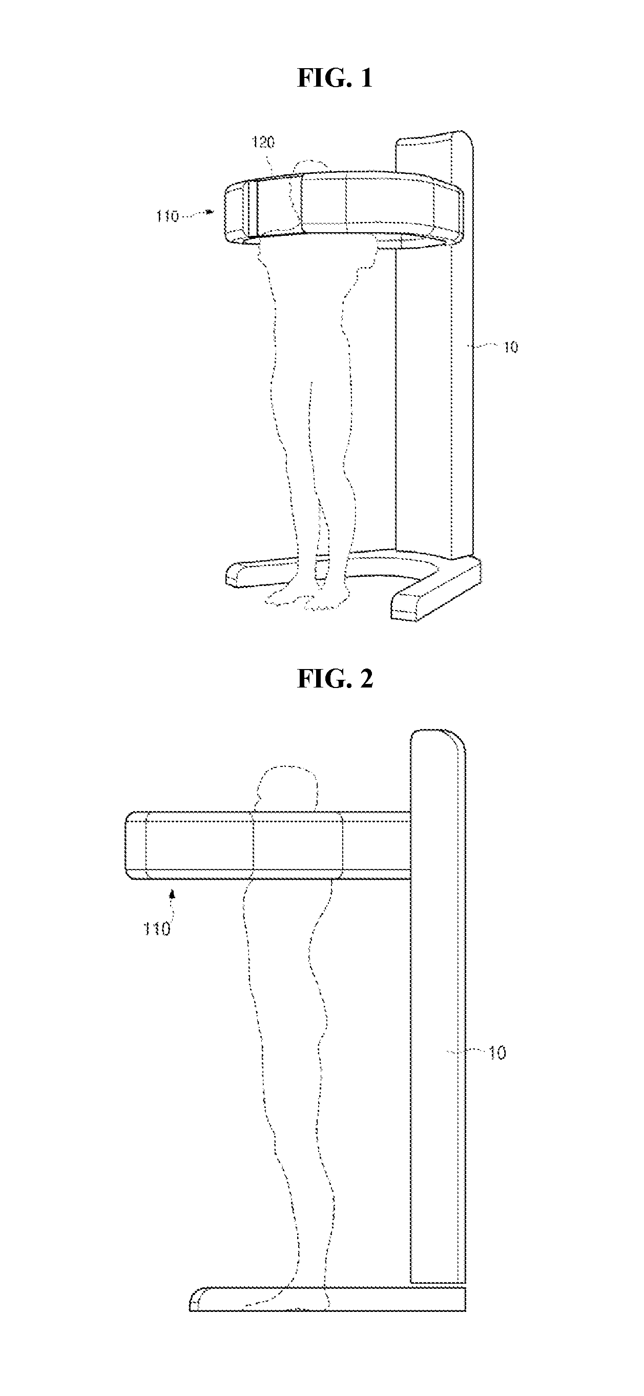
[0033]FIG. 1 is a diagram illustrating a radiography machine according to an embodiment of the present invention, FIG. 2 is a side view illustrating the radiography machine according to the embodiment of the present invention, FIG. 3 is a pl...


PUM


Abstract

The present invention relates to an imaging device for an X-ray image and, particularly, to an imaging device for an X-ray image which enables a posture of a patient to be checked and corrected in real time when an X-ray image of a specific part of a patient's body is to be imaged.

Description

TECHNICAL FIELD[0001]The present disclosure relates to a radiography machine, and more particularly, to a radiography machine which can check and correct the posture of a patient in real time when a specific body part of the patient is intended to be radiographed.BACKGROUND ART[0002]In general, during radiography, it is very important to perform radiography after checking whether the posture of a patient or a specific part of the patient is correctly positioned in an imaging area, in order to obtain a radiograph at a correct position. At this time, the posture of the patient may include various motions. For example, the patient may move the body or keep the balance, and the position of the patient in the imaging area may be corrected.[0003]According to a conventional method for measuring the posture of a patient, laser beam is irradiated on a specific part of the patient such that an operator determines whether the posture of the patient is correct. In particular, when a radiograph ...

Claims


Application Information

Patent Timeline
IPC IPC(8): A61B6/00A61B6/14A61B6/03A61B6/04
CPCA61B6/587A61B6/461A61B6/467A61B6/032A61B6/04A61B6/14A61B6/4435A61B6/51A61B6/465A61B6/469A61B6/0492A61B6/582A61B6/589A61B6/08A61B6/462
Inventor LIM, HYUNG KEUNCHUN, JIN PYO
Owner VA TECHNOLOGIE
Learn More