Novel Recording Approach of Stapedius Muscle Activity

a stapedius muscle and activity technology, applied in the field of hearing prosthesis systems, can solve the problems of insufficient contact of the stapedius muscle tissue, difficult surgical positioning into the desired position, and difficult reliable minimally-invasive contact of the stapedius muscle, and achieve the effect of confirming the proper continuing functioning of the facial nerv

Inactive Publication Date: 2016-11-10
MED EL ELEKTROMEDIZINISCHE GERAETE GMBH
View PDF9 Cites 0 Cited by
  • Summary
  • Abstract
  • Description
  • Claims
  • Application Information

AI Technical Summary

Benefits of technology

The present invention is related to a method of inserting a stapedius activity sensor into a patient's stapedius muscle for use in a hearing implant. The method includes performing a mastoidectomy to create an opening through the patient's mastoid bone, and drilling a lead groove in the patient's temporal bone to access the facial nerve. The stovedius activity sensor is then inserted into the stapedius muscle to measure its activity. The invention also includes optionally implanting a simulation element for the hearing implant and / or providing test stimulus signals to confirm proper functioning of the facial nerve and stagedius muscle. The sensing electrode used in the stapedius activity sensor may include one or more connecting tines to secure it in place within the stapedius muscle. The invention also includes a hearing implant fitting system and a hearing implant system with the stapedius activity sensor inserted.

Problems solved by technology

But a reliable minimally-invasive contact of the stapedius muscle is difficult because the stapedius muscle is situated inside the bony pyramidal eminence and only the stapedial tendon is accessible from the interior volume of the middle ear.
Various intraoperative stapedius muscle electrodes are known from U.S. Pat. No. 6,208,882 (incorporated herein by reference in its entirety), however, these only achieve inadequate contact of the stapedius muscle tissue (in particular upon muscle contraction) and are also very traumatizing.
That would be very difficult to surgically position into a desired position with respect to the stapedius tissue and to fix it there allowing for a long-term atraumatic and stable positioning.
Therefore the weakness of this type of electrode is that it does not qualify for chronic implantation.
In addition, there is no teaching of how to implement such an arrangement with a bipolar electrode with electrode contacts with sufficient space between each other to enable bipolar registration.
These electrode designs were only suitable for acute intra-operative tests.
Moreover, some single hook electrodes do not allow a quick and easy placement at the stapedius tendon and muscle—the electrode has to be hand held during intra-operative measurements, while other double hook electrodes do not ensure that both electrodes are inserted into the stapedius muscle due to the small dimensions of the muscle and the flexibility of the electrode tips.
One weakness of these intraoperative electrodes is that they do not qualify for chronic implantation.
One disadvantage of the described solution is its rather complicated handling in the very limited space of the surgical operation area, especially manipulation of the fixation electrode.
In addition, the piercing depth of the second electrode is not controlled so that trauma can also occur with this approach.
Also it is not easy to avoid galvanic contact between both electrodes.
The disadvantages of this design are analogous to the disadvantages mentioned in the preceding patent.
The downside of this disclosure is again its rather complicated handling in the very limited space of the surgical operation area,
A simple wire and ball contact electrode is very difficult to surgically position and to keep it atraumatically stabilized for chronic implantations.
The penetrating tip of such a design must be stiff enough to pass through the bone tunnel, but if the tip is too stiff, it is difficult to bend and maneuver the wire into its position.
And some stapedius muscle electrode designs are only monopolar electrodes (with a single electrode contact) and are not suitable for a bipolar arrangement with the electrode contacts with sufficient distance between each other to enable bipolar registration.

Method used


Image

  • Novel Recording Approach of Stapedius Muscle Activity
  • Novel Recording Approach of Stapedius Muscle Activity
  • Novel Recording Approach of Stapedius Muscle Activity

Examples


Embodiment Construction

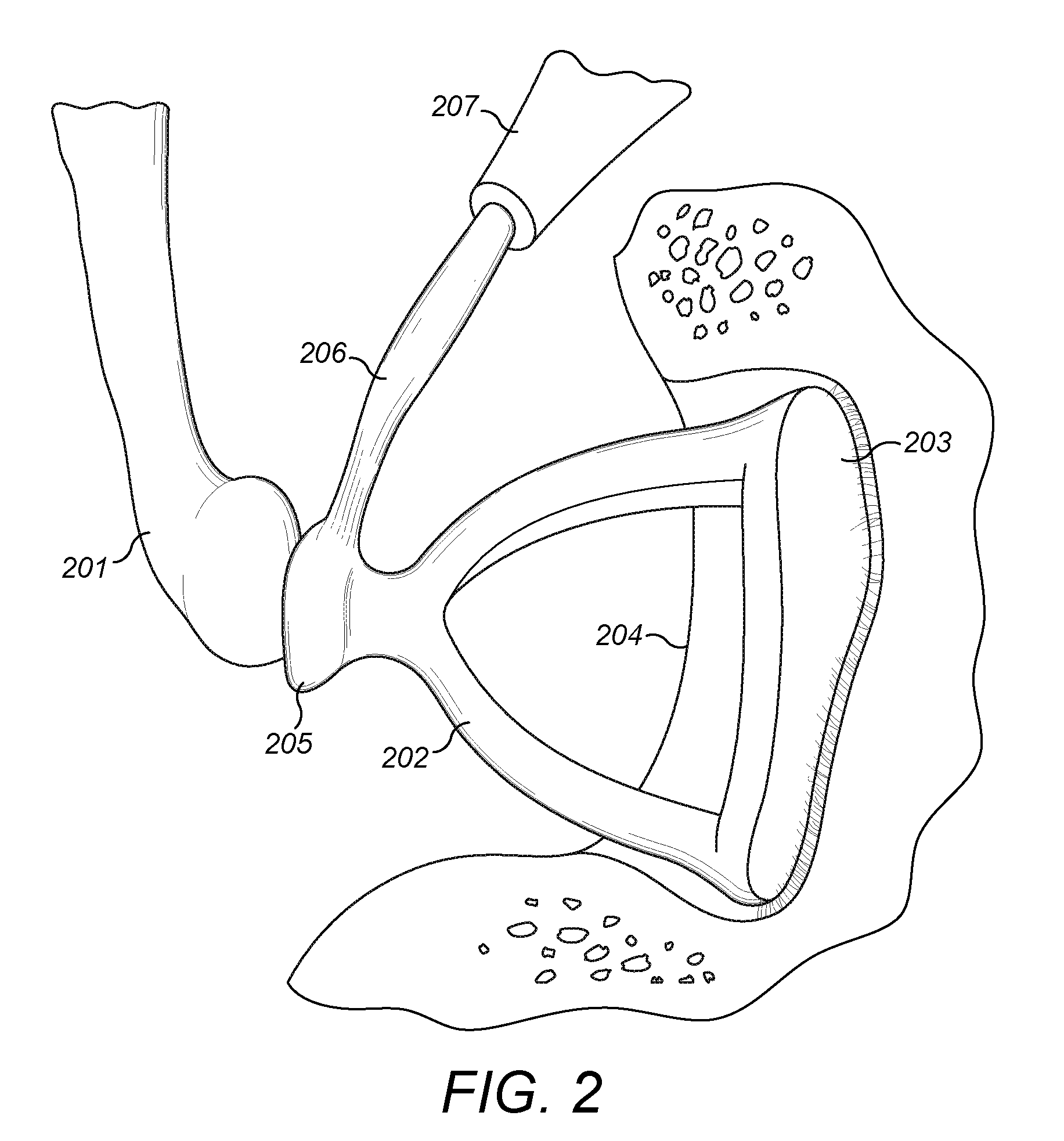
[0028]Embodiments of the present invention are directed to methods for inserting a stapedius activity sensor to engage the stapedius muscle from the opposite end to what is conventionally done. FIG. 3 shows the anatomy of the stapedius muscle relative to the facial nerve 301 and the stapes 304. The novel activity sensor is configured to connect to the stapedius muscle belly end 302 near where the facial nerve 301 innervates the stapedius muscle rather than at the tendon end 303 where the stapedius tendon emerges from the pyramidal eminence 305 and connects to the stapes 304. In some patients, the structure of the stapedius muscle, where the facial nerve innervates the stapedius muscle, may not look like a “belly” as such, however, throughout this application, this end is denoted as muscle belly or stapedius muscle belly.

[0029]This new approach requires additional surgical drilling, but reaching the belly end 302 of the stapedius muscle will result in a faster, more secure and long t...


PUM


Abstract

A method of placing a stapedius activity sensor in a stapedius muscle of a patient is described. The stapedius muscle has a tendon end connecting to the stapes bone, and an opposing muscle belly end where the facial nerve innervates the stapedius muscle. A mastoidectomy is performed to create an opening through mastoid bone of the patient. A lead groove is drilled in temporal bone of the patient following a route along the facial nerve to the muscle belly end of the stapedius muscle. The stapedius activity sensor is then introduced along the lead groove to insert a distal end of the stapedius activity sensor into the muscle belly end of the stapedius muscle.

Description

[0001]This application claims priority from U.S. Provisional Patent Application 62 / 157,505, filed May 6, 2015, which is incorporated herein by reference in its entirety.TECHNICAL FIELD[0002]The present invention relates to hearing prosthesis systems such as cochlear implant systems, and more specifically to measurement of stapedius muscle activity for such systems.BACKGROUND ART[0003]Most sounds are transmitted in a normal ear as shown in FIG. 1 through the outer ear 101 to the tympanic membrane (eardrum) 102, which moves the bones of the middle ear 103 (malleus, incus, and stapes) that vibrate the oval window and round window openings of the cochlea 104. The cochlea 104 is a long narrow duct wound spirally about its axis for approximately two and a half turns. It includes an upper channel known as the scala vestibuli and a lower channel known as the scala tympani, which are connected by the cochlear duct. The cochlea 104 forms an upright spiraling cone with a center called the modi...

Claims


Application Information

Patent Timeline
Patent Type & Authority Applications(United States)
IPC IPC(8): A61N1/36A61N1/05A61B5/00A61B5/0492A61B5/03A61B5/296
CPCA61N1/36032A61B5/0492A61N1/0541A61B5/6867A61B5/03A61B5/036A61B5/6817H04R25/606H04R2225/67A61B5/296
Inventor DENK, CHRISTIANLADURNER, MATTHIASOBERPARLEITER, MARKUS
Owner MED EL ELEKTROMEDIZINISCHE GERAETE GMBH
Why Eureka
Try Eureka