
Method for determining the orientation of a sensor frame of reference tied to a mobile terminal furnished with a sensor assembly, carried or worn by a user and comprising at least one motion tied motion sensor

a technology of motion sensor and orientation, which is applied in the direction of navigation instruments, speed/acceleration measurement, instruments, etc., can solve the problems of ineffective or defective gnss techniques, rather unadvantageous electrical consumption budget, inaccurate or noisy positions,

Active Publication Date: 2016-10-27
MOVEA
View PDF8 Cites 16 Cited by
  • Summary
  • Abstract
  • Description
  • Claims
  • Application Information

AI Technical Summary

Benefits of technology

This invention allows for the accurate tracking of a person's movement by attaching a reference frame to the ground and using sensors on the person's body. This reference frame is then compared to the frame that the person is walking in, allowing for the determination of the person's orientation and the direction they are facing. This technology uses a technique called matched filtering to accurately compute the frequency of the accelerometer signal on the person's body. This allows for the tracking of the person's movement without the need for other devices or sensors.

Problems solved by technology

Indoors, or in urban environments where several satellites may be hidden (so-called “urban canyon” effect), GNSS techniques may turn out to be inoperative or defective.
Moreover, they exhibit a rather unadvantageous electrical consumption budget.
The use of the radio signals (GSM, WIFI, etc.) transmitted and received by a mobile telephone can also be utilized, including indoors, to locate pedestrians in an absolute manner with respect to the points of radio access but they generate rather inaccurate or noisy positions (at best 100 meters for the GSM radio signal, errors of several tens of meters are possible for WIFI, with notably position jumps from one instant to the next), they are dependent on the equipment in situ, and exhibit an unfavorable consumption budget.
However, in the case of the pedestrian, the heading is not easy to estimate, insofar as, if the system of sensors actually makes it possible to measure an orientation (and therefore a heading) of the sensor system in the reference frame (or to fix matters, of the terrestrial frame), it is not possible to simply link this orientation to the heading followed by the pedestrian.
Indeed, depending on the way in which the pedestrian carries or wears the sensor, and multiple possibilities are noted, able in addition to vary over time, it appears a priori that it is not possible to establish any relationship between the heading of the trajectory and the orientation of the sensor in the terrestrial frame.
However, this constraining procedure hampers the adoption of location solutions based on the principle of inertial sensors, and on the other hand, there is no guarantee of the user being capable of keeping to the command.
Indeed, the position of the accessory on the waist does not of itself make it possible to guarantee the relation between the orientation of this accessory and the heading of the pedestrian.
This problem consisting in determining the relationship between sensor and trajectory, called for example “sensor-to-trajectory” or “sensor-to-traj” or “angle misalignment”, is very complex.
Moreover, the vertical direction identified in a rest period is no longer valid as soon as a motion which substantially modifies the orientation of the sensor housing is generated.
The combination of the two, according to the user's gait, according to the position of the sensor does not afford any guarantee that this resulting horizontal acceleration is always oriented in the direction of walking.
It should however be noted that a pedestrian in a walking or running situation generates accelerations in the direction of the trajectory and also in directions perpendicular to the trajectory and that the combination of the two can generate resultants in all directions and that the result is then completely uncertain.
However, the articulation of this technique with the previous principle does not seem very clear.
Moreover, it seems complex to have firstly to classify a sensor position on the body in order to apply the procedure thereafter.
This multisensor fusion is complex, it requires a classification stage, itself error prone, in order to produce results.
Moreover, by definition of the low-frequency components, the procedure obtains an average direction of the vertical, which is not applicable to the motion as a whole.
The extraction of the horizontal components does not therefore seem to be possible, if the motion comprises substantial rotations.
Here again, the assumption upon which the method rests is fragile.
The principal weakness of all these approaches resides in their robustness, in particular in the assumption that the measured accelerations are carried by the direction of displacement, while the accelerations generated by the motion of a pedestrian in a walking or running situation generate transverse as well as longitudinal accelerations.
A problem is that the notion of duration is in contradiction with that of real time which is central for the applications envisaged.
Moreover, for example, if a user changes the position sensor, it will only be possible for the new position to be determined accurately after a duration T such that the accelerometer signal collected over this duration contains several cycles of footsteps.

Method used


Image

  • Method for determining the orientation of a sensor frame of reference tied to a mobile terminal furnished with a sensor assembly, carried or worn by a user and comprising at least one motion tied motion sensor
  • Method for determining the orientation of a sensor frame of reference tied to a mobile terminal furnished with a sensor assembly, carried or worn by a user and comprising at least one motion tied motion sensor
  • Method for determining the orientation of a sensor frame of reference tied to a mobile terminal furnished with a sensor assembly, carried or worn by a user and comprising at least one motion tied motion sensor

Examples


Embodiment Construction

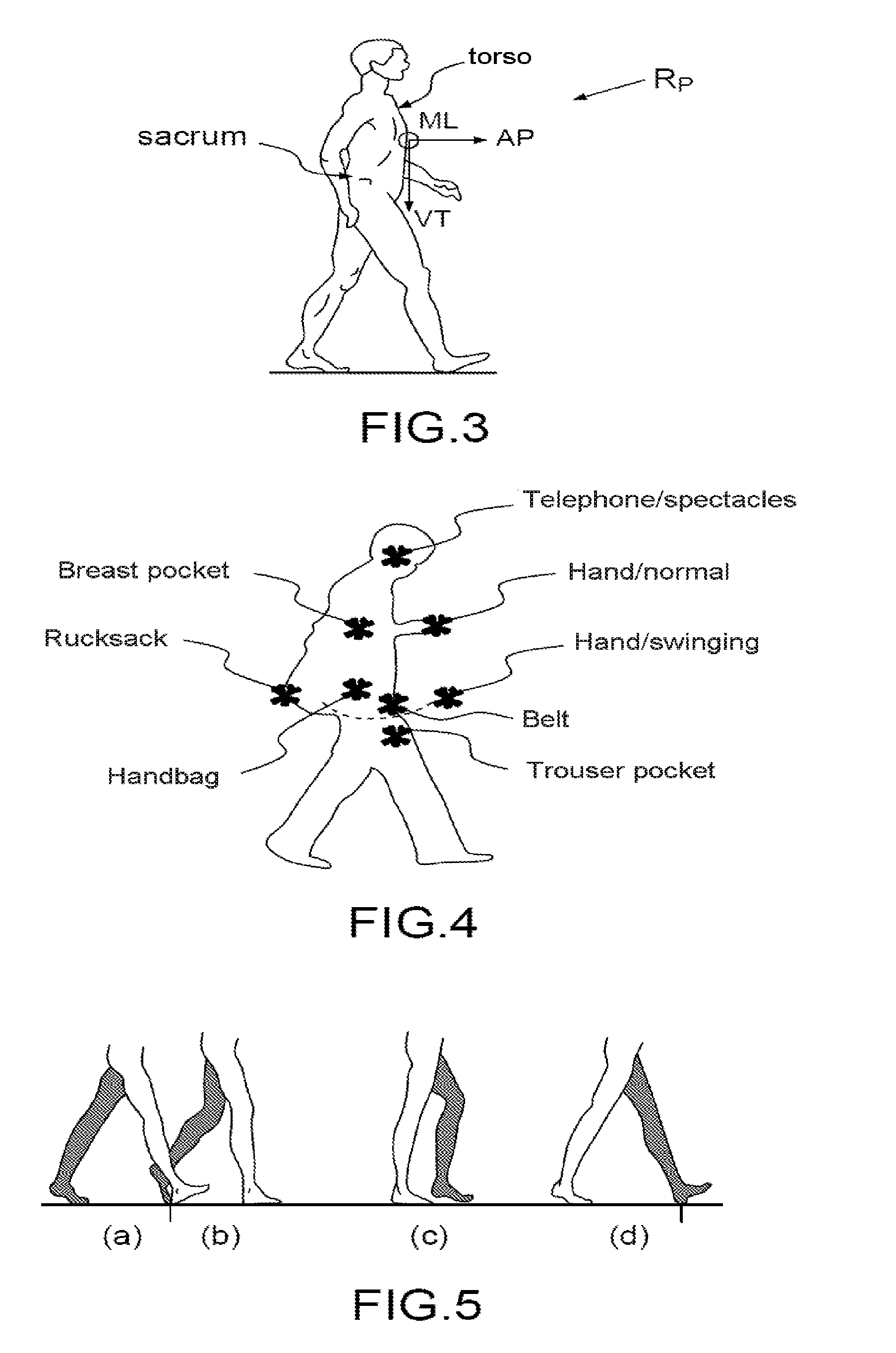
[0110]In the set of figures, the elements having the same references are similar.

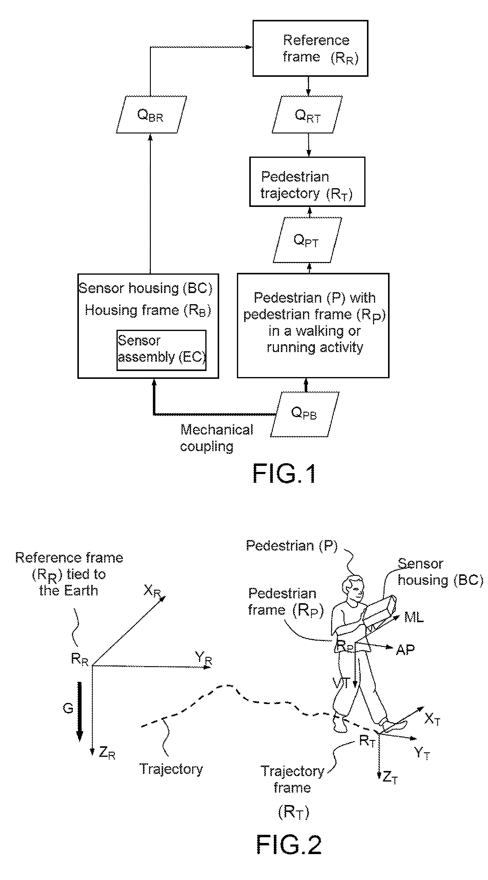
[0111]FIG. 1 schematically illustrates a pedestrian system and the manner of operation thereof according to an aspect of the invention, and notably the various frames used and their relations.

[0112]A sensor housing BC comprises a sensor assembly EC furnished with at least one motion sensor. A housing frame RB is associated with the sensor housing BC.

[0113]A reference frame RR is also determined. A rotation transformation operator for rotating between the housing frame RB and the reference frame RR is denoted QBR. This operator may evolve over time.

[0114]A pedestrian P is furnished with a pedestrian frame RP. A trajectory frame RT is associated with the trajectory followed by the pedestrian P. An operator QPT between the trajectory frame and the pedestrian frame is defined. This operator is defined by convention of the pedestrian frame RP and trajectory frame RT.

[0115]The pedestrian P and the sensor hous...


PUM


Abstract

Method for determining the orientation of the trajectory followed by a pedestrian, associated with a trajectory frame, with respect to a reference frame, said pedestrian being furnished with a sensor housing comprising a sensor assembly comprising at least one motion sensor, comprising the steps consisting in:generating data representative of the motion of the sensor housing on the basis of said sensor assembly in the reference frame, andcomputing the value of a first rotation transformation operator representative of the orientation of the reference frame with respect to the trajectory frame, in such a way that the data representative of the motion which are thus obtained in the previous step, in the reference frame, and transformed by said first operator, exhibit at least one characteristic of a set of characteristics which are representative of signals of walking or running motion of a pedestrian and are expressed in the pedestrian frame.

Description

FIELD OF THE INVENTION[0001]The invention pertains to a method for determining the orientation of the trajectory followed by a pedestrian, associated with a trajectory frame, with respect to a reference frame, the pedestrian being furnished with a sensor housing comprising a sensor assembly comprising at least one motion sensor.TECHNICAL BACKGROUND OF THE INVENTION[0002]A method for determining the orientation of the trajectory followed by a pedestrian, associated with a trajectory frame, with respect to a reference frame, by means of a sensor assembly comprising at least one motion sensor, with which the pedestrian is furnished, can be useful in diverse applications such as pedestrian navigation, be it indoors or outdoors, for which it is necessary to locate the pedestrian and / or determine his trajectory. The pedestrian can undertake a walking or running activity. Several techniques are known for locating a pedestrian in an absolute manner on a plane. It is for example possible to ...

Claims


Application Information

Patent Timeline
Patent Type & Authority Applications(United States)
IPC IPC(8): G01C21/20G01P15/08G01P13/00G01C21/16G01C21/18
CPCG01C21/20G01C21/206G01P15/08G01C21/18G01P13/00G01C21/16G01C21/166
Inventor LEMARCHAND, ANTOINEDE FORAS, ETIENNE
Owner MOVEA
Learn More