
Heart Valve Assembly

a heart valve and assembly technology, applied in the field of heart valve assembly, can solve the problems of heart valves being less effective, serious cardiovascular compromise or death, dangerous surgeries, and prone to complications

Active Publication Date: 2016-10-27
VENUS MEDTECH (HANGZHOU) INC
View PDF1 Cites 43 Cited by
  • Summary
  • Abstract
  • Description
  • Claims
  • Application Information

AI Technical Summary

Benefits of technology

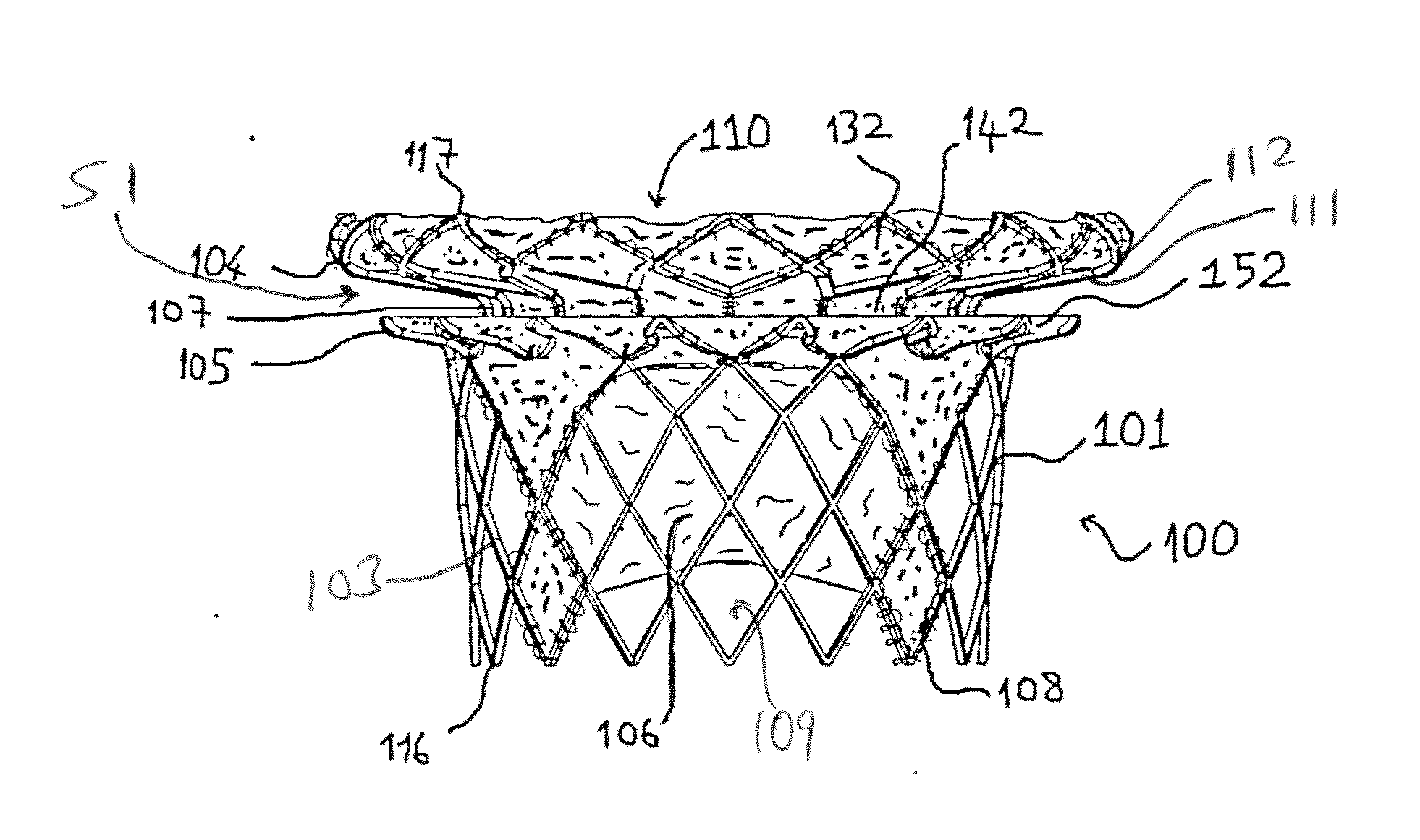
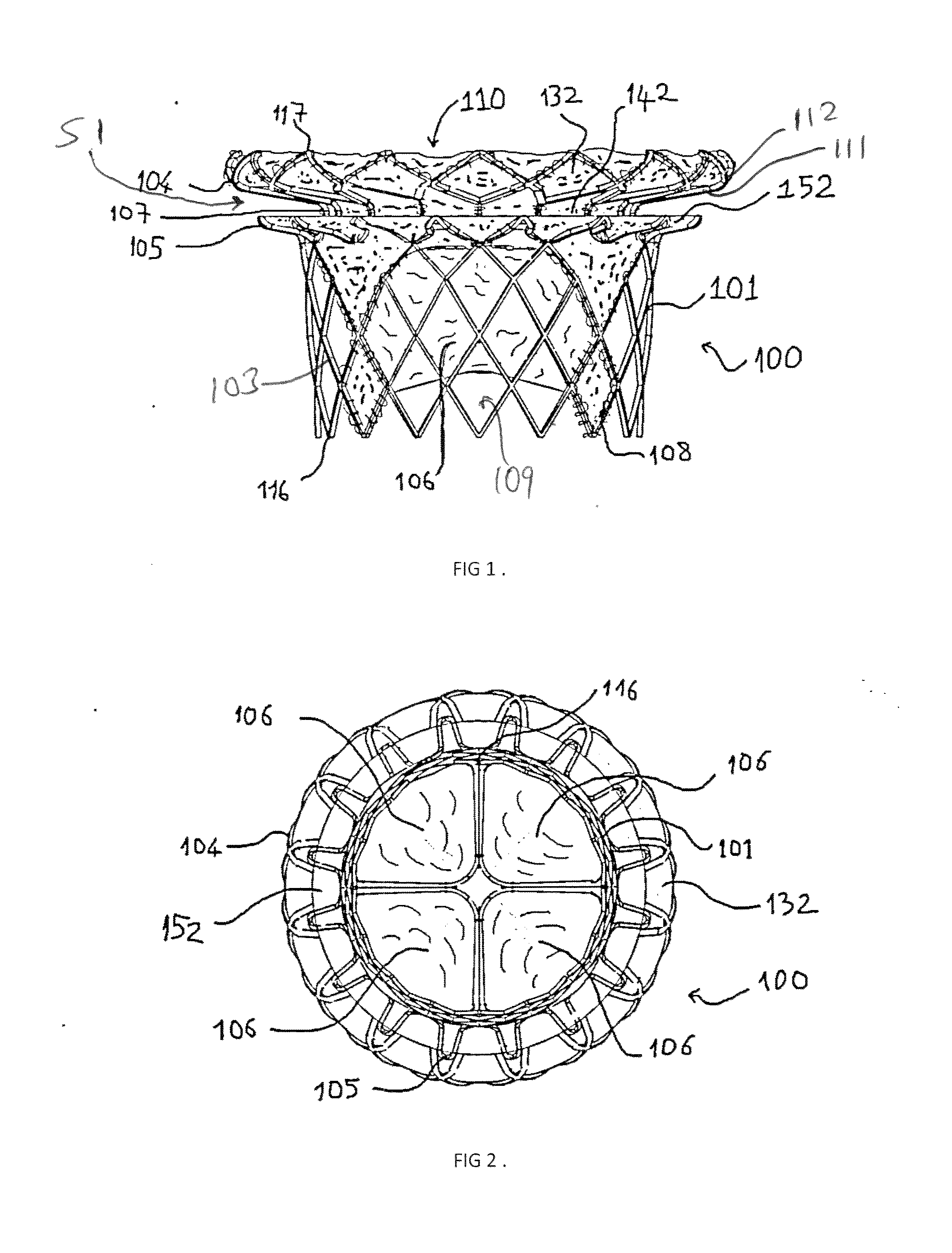
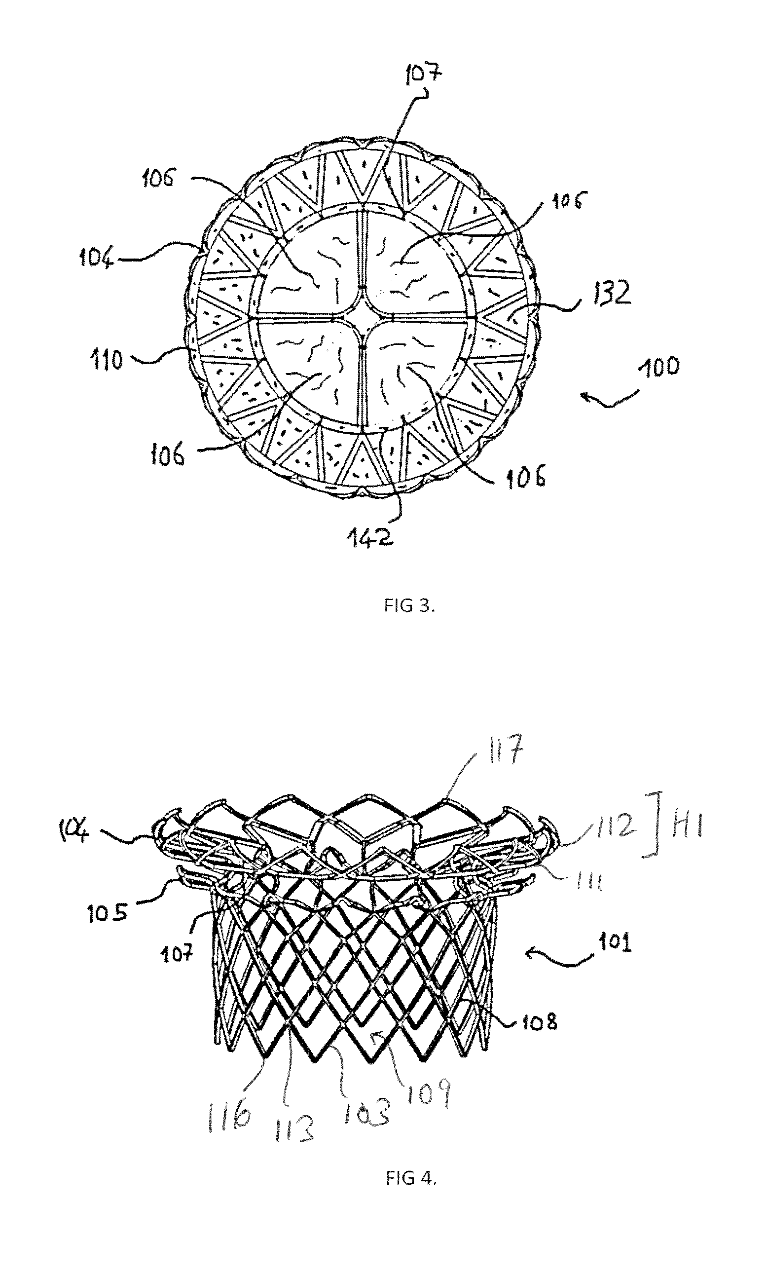
The present invention provides a heart valve assembly comprising a wire frame and a leaflet assembly. The wire frame has a cylindrical valve support section and a neck section that transitions between the anchor section and the valve support section. The anchor section has an annular flange that extends radially therefrom, creating an annular space between the flange and the supports for receiving or capturing the native annulus when the heart valve is deployed. The leaflet assembly has a plurality of leaflets stitched to the valve support section and positioned on the inflow side of the neck section. The heart valve can be secured at the location of the native annulus of a human heart by delivering the heart valve assembly to the location of a native annulus, and deploying the heart valve assembly at the location of the native annulus with the native annulus retained inside the annular space. The technical effects of this invention include a heart valve assembly that can provide a reliable and secure method of replacing a failed heart valve without the need for open-heart surgery.

Problems solved by technology

These heart valves can be rendered less effective by congenital, inflammatory, or infectious conditions.
Such conditions can eventually lead to serious cardiovascular compromise or death.
For many years the definitive treatment for such disorders was the surgical repair or replacement of the valve during open heart surgery, but such surgeries are dangerous and prone to complication.
Unlike the aortic valve, however, the mitral valve annulus does not provide a good landmark for positioning a replacement mitral valve.
The thinner mitral valve annulus makes it relatively more difficult to properly seat a replacement mitral valve in the native mitral valve annulus.
The general anatomy of the mitral valve annulus also makes it more difficult to properly anchor a replacement mitral valve in place.
Thus, the larger mitral valve annulus makes it difficult to securely implant current percutaneously delivered valves in the native mitral position.
Some attempts have been made to deliver and implant a one-piece replacement mitral valve, but it is difficult to provide a device that can be collapsed down to have a sufficiently small delivery profile and still be able to be expanded and secured in place within the mitral valve via a vascular access site.

Method used


Image

  • Heart Valve Assembly
  • Heart Valve Assembly
  • Heart Valve Assembly

Examples


Embodiment Construction

[0028]The following detailed description is of the best presently contemplated modes of carrying out the invention. This description is not to be taken in a limiting sense, but is made merely for the purpose of illustrating general principles of embodiments of the invention. The scope of the invention is best defined by the appended claims.

[0029]The present invention provides a mitral valve device 100 that is shown in fully assembled form in FIGS. 1-3. The device 100 has a wire frame 101 (see FIGS. 4-6) that is adapted to carry an integrated leaflet assembly that comprises a plurality of leaflets 106. The wire frame 101 provides a simple leaflet valve support structure that can be effectively secured at the native mitral valve annulus. The overall construction of the device 100 is simple, and effective in promoting proper mitral valve function.

[0030]As shown in FIGS. 4-6, the wire frame 101 comprises an (outflow) anchor section 104 that transitions to a generally cylindrical valve s...


PUM


Abstract

A heart valve assembly has a heart valve assembly that has a wire frame comprising an anchor section, a generally cylindrical valve support section, and a neck section that transitions between the anchor section and the valve support section. The wire frame includes a plurality of supports extending radially outwardly in an annular manner about an upper end of the valve support section, and the anchor section has an annular flange that extends radially therefrom, so that an annular space is defined between the annular flange and the annular supports for receiving or capturing the native annulus when the heart valve is deployed. The heart valve assembly also includes a leaflet assembly having a plurality of leaflets that are stitched to the valve support section and which are positioned on an inflow side of the neck section.

Description

BACKGROUND OF THE INVENTION[0001]1. Field of the Invention[0002]The present invention is directed to methods, systems, and apparatus for safely replacing or repairing native heart valves with prosthetic heart valves.[0003]2. Description of the Prior Art[0004]Prosthetic heart valves have been used for many years to treat cardiac valvular disorders. The native heart valves (such as the aortic, pulmonary, and mitral valves) serve critical functions in assuring the forward flow of an adequate supply of blood through the cardiovascular system. These heart valves can be rendered less effective by congenital, inflammatory, or infectious conditions. Such conditions can eventually lead to serious cardiovascular compromise or death. For many years the definitive treatment for such disorders was the surgical repair or replacement of the valve during open heart surgery, but such surgeries are dangerous and prone to complication.[0005]More recently a transvascular technique has been developed fo...

Claims


Application Information

Patent Timeline
Patent Type & Authority Applications(United States)
IPC IPC(8): A61F2/24
CPCA61F2/2418A61F2220/0075A61F2220/0008A61F2/2409A61F2/2436A61F2230/0052A61F2250/0039A61F2250/0069A61F2230/0065A61F2220/0033A61F2230/0013A61F2230/005A61F2230/0054A61F2230/0078A61F2250/0063
Inventor ZENG, MIN FRANKLO, PHAM
Owner VENUS MEDTECH (HANGZHOU) INC
Learn More