Enhanced cooling for blade tip

a technology of enhanced cooling and blade tip, which is applied in the direction of efficient propulsion technology, machines/engines, stators, etc., can solve the problems of difficult to effectively cool the tip of the airfoil, the temperature of the gas path may exceed, and the inability to effectively cool the leading edge portion of the tip

Active Publication Date: 2016-10-13
RAYTHEON TECH CORP
View PDF13 Cites 6 Cited by
  • Summary
  • Abstract
  • Description
  • Claims
  • Application Information

AI Technical Summary

Benefits of technology

[0022]In another embodiment according to any of the previous embodiments, the first radius is greater than the se

Problems solved by technology

This can result in gas path temperatures that may exceed melting points of turbine component materials.
One area that is difficult to effectively cool is a tip of the airfoil.
Tip shel

Method used


Image

  • Enhanced cooling for blade tip
  • Enhanced cooling for blade tip
  • Enhanced cooling for blade tip

Examples


Embodiment Construction

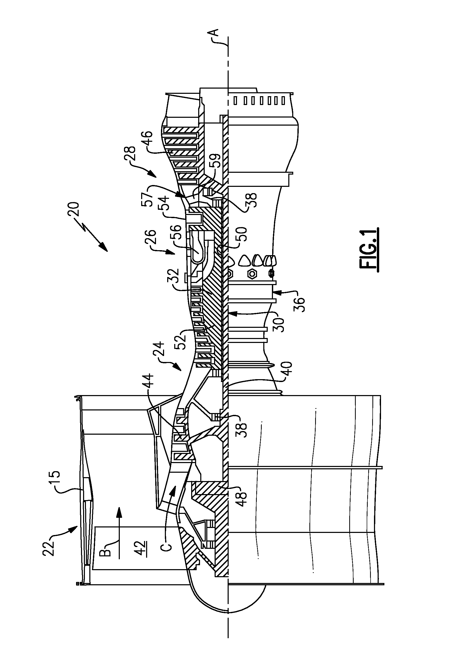
[0034]FIG. 1 schematically illustrates a gas turbine engine 20. The gas turbine engine 20 is disclosed herein as a two-spool turbofan that generally incorporates a fan section 22, a compressor section 24, a combustor section 26 and a turbine section 28. Alternative engines might include an augmentor section (not shown) among other systems or features. The fan section 22 drives air along a bypass flow path B in a bypass duct defined within a nacelle 15, while the compressor section 24 drives air along a core flow path C for compression and communication into the combustor section 26 then expansion through the turbine section 28. Although depicted as a two-spool turbofan gas turbine engine in the disclosed non-limiting embodiment, it should be understood that the concepts described herein are not limited to use with two-spool turbofans as the teachings may be applied to other types of turbine engines including three-spool architectures.

[0035]The exemplary engine 20 generally includes ...


PUM


Abstract

In a featured embodiment, a gas turbine engine component comprises an airfoil having a leading edge, a trailing edge, and pressure and suction side walls extending from the leading edge to the trailing edge. The airfoil extends from a base to a tip. A shelf is formed in the tip, and extends from the pressure side wall, around the leading edge, to the suction side wall.

Description

CROSS-REFERENCE TO RELATED APPLICATION[0001]This application claims priority to U.S. Provisional Patent Application No. 61 / 916,980, filed Dec. 17, 2013.BACKGROUND OF THE INVENTION[0002]In pursuit of higher engine efficiencies, higher turbine inlet temperatures have been relied upon to boost overall engine performance. This can result in gas path temperatures that may exceed melting points of turbine component materials. To address this issue, dedicated cooling air is extracted from a compressor section and is used to cool the gas path components in the turbine, such as rotating blades and stator vanes for example.[0003]One method of cooling turbine airfoils utilizes internal cooling passages. Typically, film cooling holes and significant volumes of cooling air are required to provide the needed amount of cooling. One area that is difficult to effectively cool is a tip of the airfoil. Tip shelves and squealer pockets have been incorporated into the tip of the blade to improve cooling...

Claims


Application Information

Patent Timeline
IPC IPC(8): F01D5/18F02C7/18F01D9/02F02C3/04
CPCF01D5/186F02C3/04F02C7/18F01D9/02F05D2240/35F05D2260/202F05D2240/305F05D2240/306F05D2240/303F05D2220/32F01D5/20F01D5/187F05D2240/307F05D2250/71Y02T50/60
Inventor AUXIER, JAMES T.SLAVENS, THOMAS N.DONNELL, BRANDON S.GIRMA, YAFET
Owner RAYTHEON TECH CORP
Why Eureka
Try Eureka