Zoom lens apparatus and method of controlling same

a zoom lens and apparatus technology, applied in the direction of printers, instruments, cameras, etc., can solve the problems of degrading image quality, no consideration is given to correcting for the change of aberration that accompanies zooming, and affecting the quality of images, so as to achieve the effect of reducing astigmatism

Inactive Publication Date: 2016-09-29
FUJIFILM CORP
View PDF2 Cites 0 Cited by
  • Summary
  • Abstract
  • Description
  • Claims
  • Application Information

AI Technical Summary

Benefits of technology

[0008]An object of the present invention is to alleviate astigmatism that accompanies zooming.
[0022]In accordance with the present invention, at least one lens is tilted (with respect to the optical axis of the zoom lens apparatus) at a tilt angle corresponding to the zoom magnification. Even if a group of zoom lenses moves along the optical axis in accordance with the zoom magnification, the lenses can be tilted at such a tilt angle for which astigmatism is mitigated in accordance with movement of the lenses. Astigmatism can be reduced irrespective of the zoom magnification.

Problems solved by technology

There are instances where aberration occurs in a zoom lens apparatus in the process of manufacturing and assembling the lens.
Even if it is attempted to suppress fluctuating aberration by an adjustment performed at the time of assembly of the zoom lens, with a zoom lens used in a very high-definition television broadcast, there are cases where astigmatism, which accompanies zooming, occurs on the order of 0.1 in terms of Newton's rings, thereby resulting in degraded image quality.
However, no consideration is given to correcting for a change in aberration that accompanies zooming.

Method used


Image

  • Zoom lens apparatus and method of controlling same
  • Zoom lens apparatus and method of controlling same
  • Zoom lens apparatus and method of controlling same

Examples


Embodiment Construction

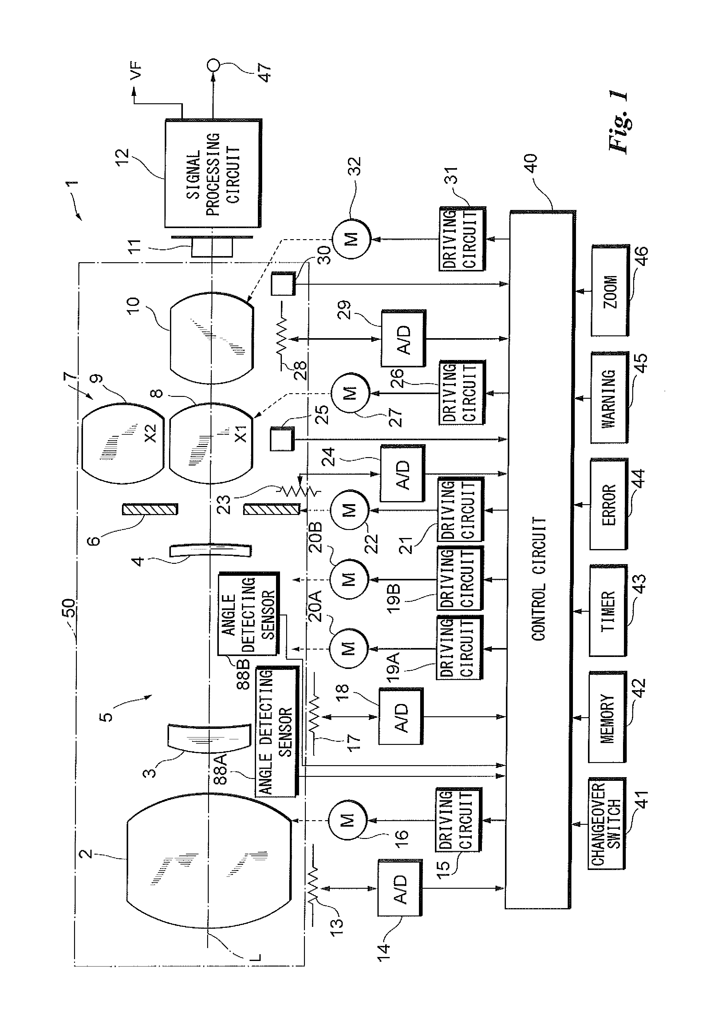
[0040]FIG. 1 is a block diagram illustrating the electrical configuration of a lens (zoom lens apparatus) 1 for a television camera having a zoom lens barrel.

[0041]The overall operation of the lens 1 for the television camera is controlled by a control circuit 40.

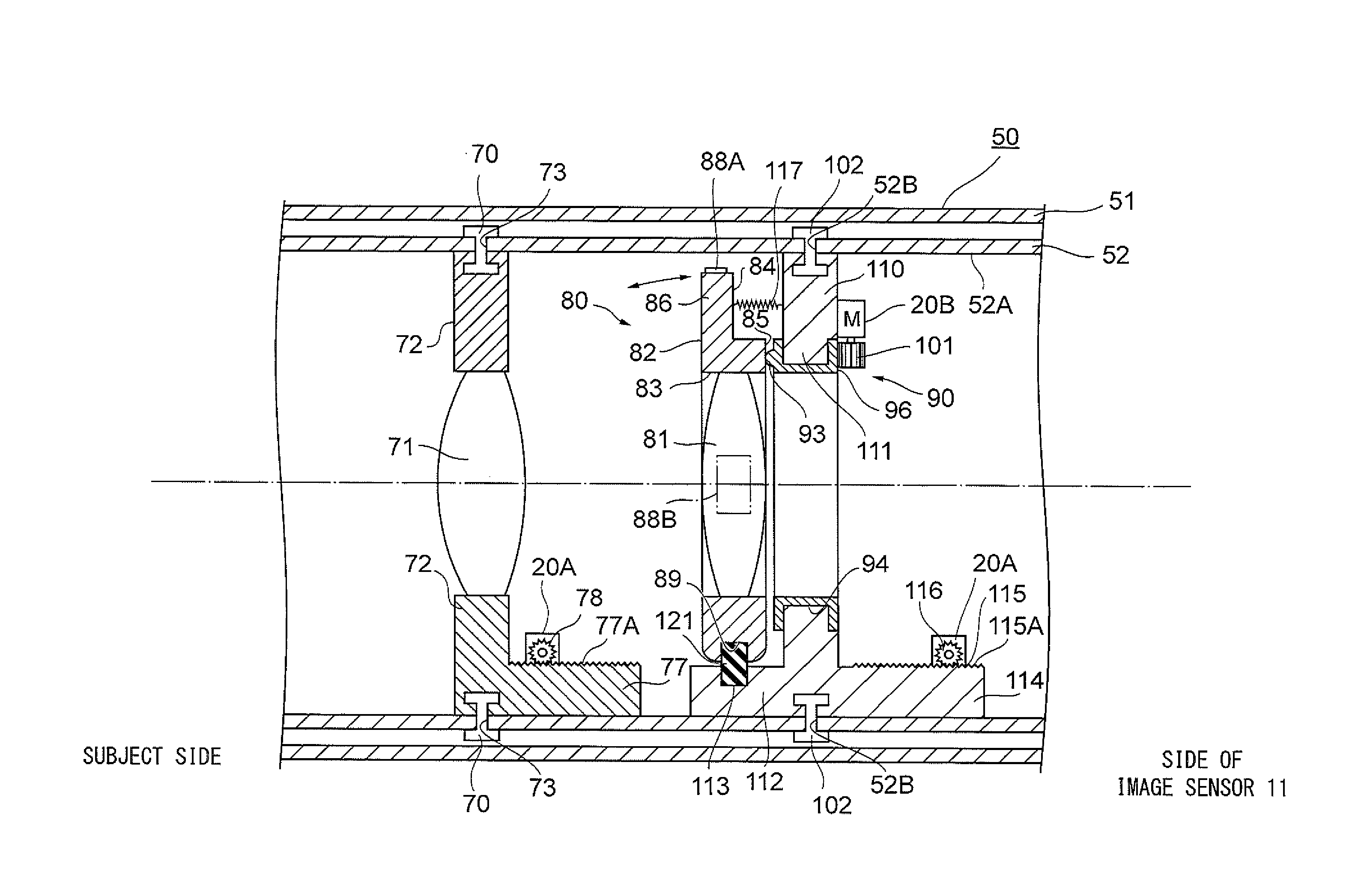
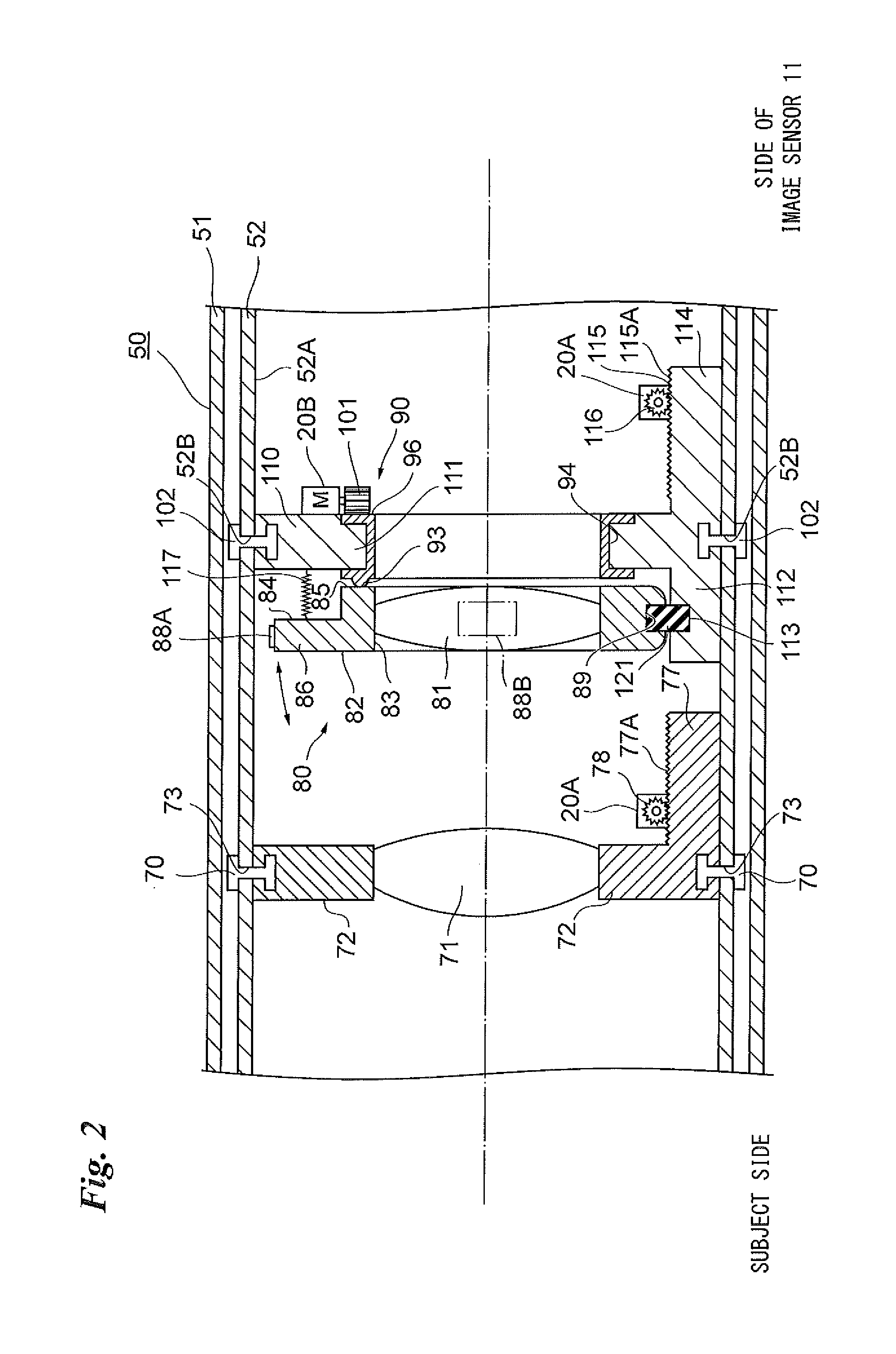
[0042]The TV camera lens 1 includes an image sensor 11. A zoom lens barrel 50 is disposed on the side of the photoreceptor surface of the image sensor 11. Placed in the zoom lens barrel 50 are a focusing optical system 2 that includes one lens or multiple lenses (the focusing optical system 2 also is a lens group constituted by two or more lenses); a zoom optical system (a lens group constituted by two or more lenses) 5 for changing zoom magnification; a diaphragm 6; an extender lens (group) 7 and a master optical system 10 (the master optical system 10 also is a lens group constituted by two or more lenses). The TV camera lens 1 has an optical axis L that passes through the centers of the focusing optical system 2, zoom op...


PUM


Abstract

Provided are a zoom lens apparatus as well as a method of controlling the apparatus for alleviating astigmatism. A lens is moved along the direction of the optical axis of the zoom lens apparatus in accordance with zoom magnification. The angle of rotation of a ring that rotates about the optical axis of the zoom lens apparatus is read from a table stored in advance. The ring is rotated through the read angle of rotation. A lens holding frame holding the lens has a surface is contact with the ring, and the surface has protrusions and cavities so that when the ring is rotated, the lens holding frame is tilted and so is the lens. The tilt angle is decided in such a manner that astigmatism is reduced in accordance with zoom magnification. Astigmatism is reduced even though the lens is moved in accordance with zoom magnification.

Description

CROSS-REFERENCE TO RELATED APPLICATIONS[0001]The present invention claims priority under 35 U.S.C. §119 to Japanese Patent Application No. 2015-064584 filed Mar. 5, 2015. Each of the above application(s) is hereby expressly incorporated by reference, in its entirety, into the present application.BACKGROUND OF THE INVENTION[0002]1. Field of the Invention[0003]This invention relates to a zoom lens apparatus and to a method of controlling such apparatus.[0004]2. Description of the Related Art[0005]There are instances where aberration occurs in a zoom lens apparatus in the process of manufacturing and assembling the lens. Even if it is attempted to suppress fluctuating aberration by an adjustment performed at the time of assembly of the zoom lens, with a zoom lens used in a very high-definition television broadcast, there are cases where astigmatism, which accompanies zooming, occurs on the order of 0.1 in terms of Newton's rings, thereby resulting in degraded image quality. Further, th...

Claims


Application Information

Patent Timeline
Patent Type & Authority Applications(United States)
IPC IPC(8): G02B27/00G03B5/06G02B7/10
CPCG02B27/0025G03B5/06G02B7/10G02B7/04G02B27/646G02B7/102G02B15/04G03B3/10G03B2205/00G03B2205/0046
Inventor ISHII, YOSHIAKI
Owner FUJIFILM CORP
Why Eureka
Try Eureka