
Balancing device for arthroplasty and methods for use

a technology of balancing device and arthroplasty, which is applied in the field of balancing device for arthroplasty, can solve the problems of limited range of motion of the joint, continued pain at the joint, and early failure of the artificial join

Active Publication Date: 2016-09-29
XPANDORTHO
View PDF16 Cites 34 Cited by
  • Summary
  • Abstract
  • Description
  • Claims
  • Application Information

AI Technical Summary

Benefits of technology

The patent describes a device and method for balancing joints during surgical procedures, specifically for prosthetic arthroplasty. The device includes an insert with plates and sensors that provide data on the movement of the joint. It also includes an actuator for applying force to the joint. The device can be used to balance the joint during repair procedures and can be customized based on the specific needs of each patient. The technical effects of the patent include improved accuracy and dynamic adjustments to the joint, improved outcomes based on real-time control and visualized feedback, and the ability to measure and adjust various parameters relating to the joint.

Problems solved by technology

As a result, the process of balancing the joint is largely subjective, as it relies upon the experience and knowledge of the surgeon to understand whether the movement of the artificial joint is “about right.” Misalignment of any of these parameters may result in limited range of motion of the joint, continued pain at the joint and early failure of the artificial joint due to excess load distribution or friction.
Even with these measurement devices, the surgeon is still required to manually apply an unknown or inaccurate force to the joint in order to determine whether the joint is balanced.
If the amount of applied force is inconsistent with the actual force applied to the joint during actual use, the joint may not move appropriately and may wear prematurely, leading to limited movement, pain, and eventual replacement or further surgical repairs.

Method used


Image

  • Balancing device for arthroplasty and methods for use
  • Balancing device for arthroplasty and methods for use
  • Balancing device for arthroplasty and methods for use

Examples


Embodiment Construction

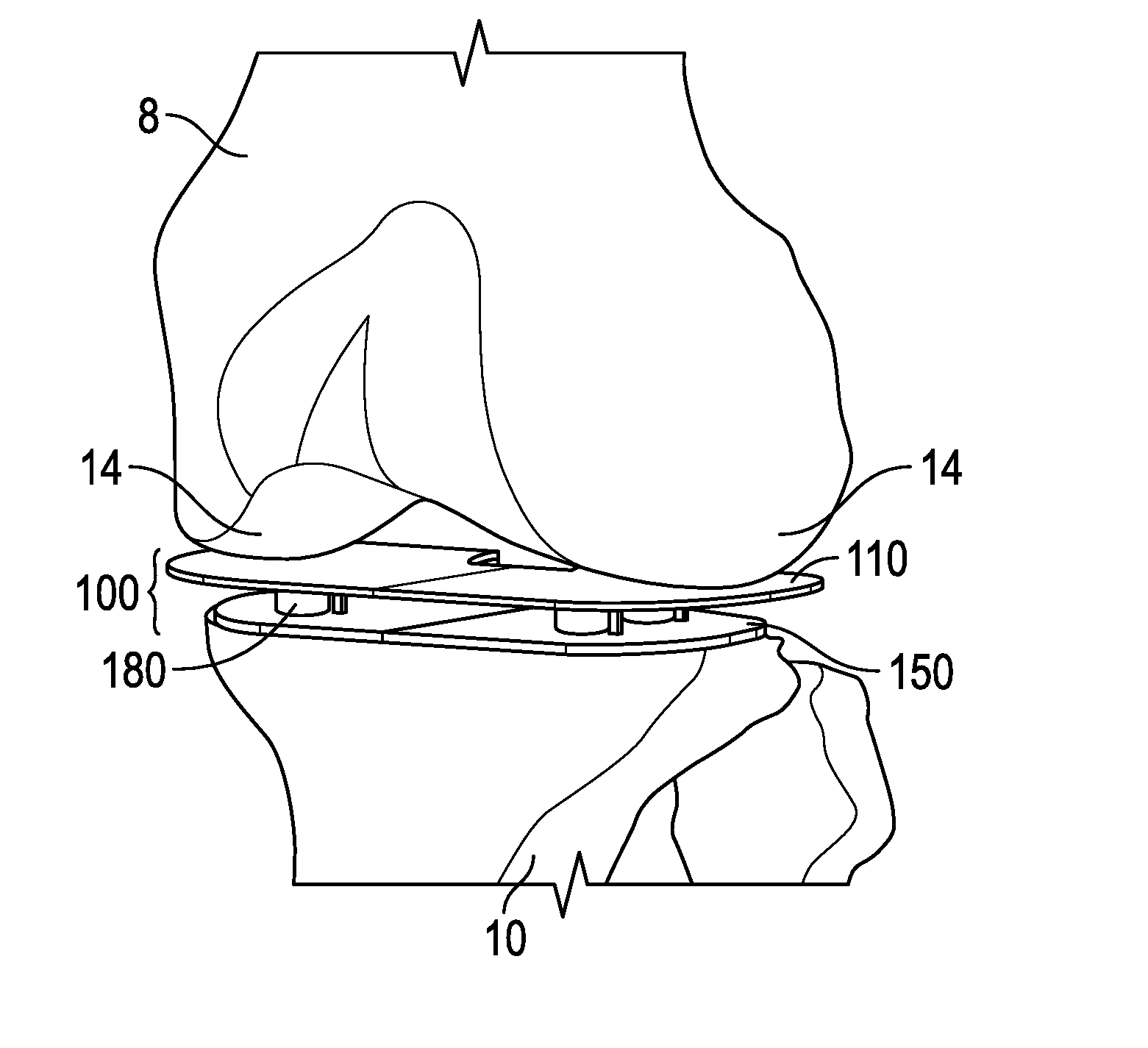
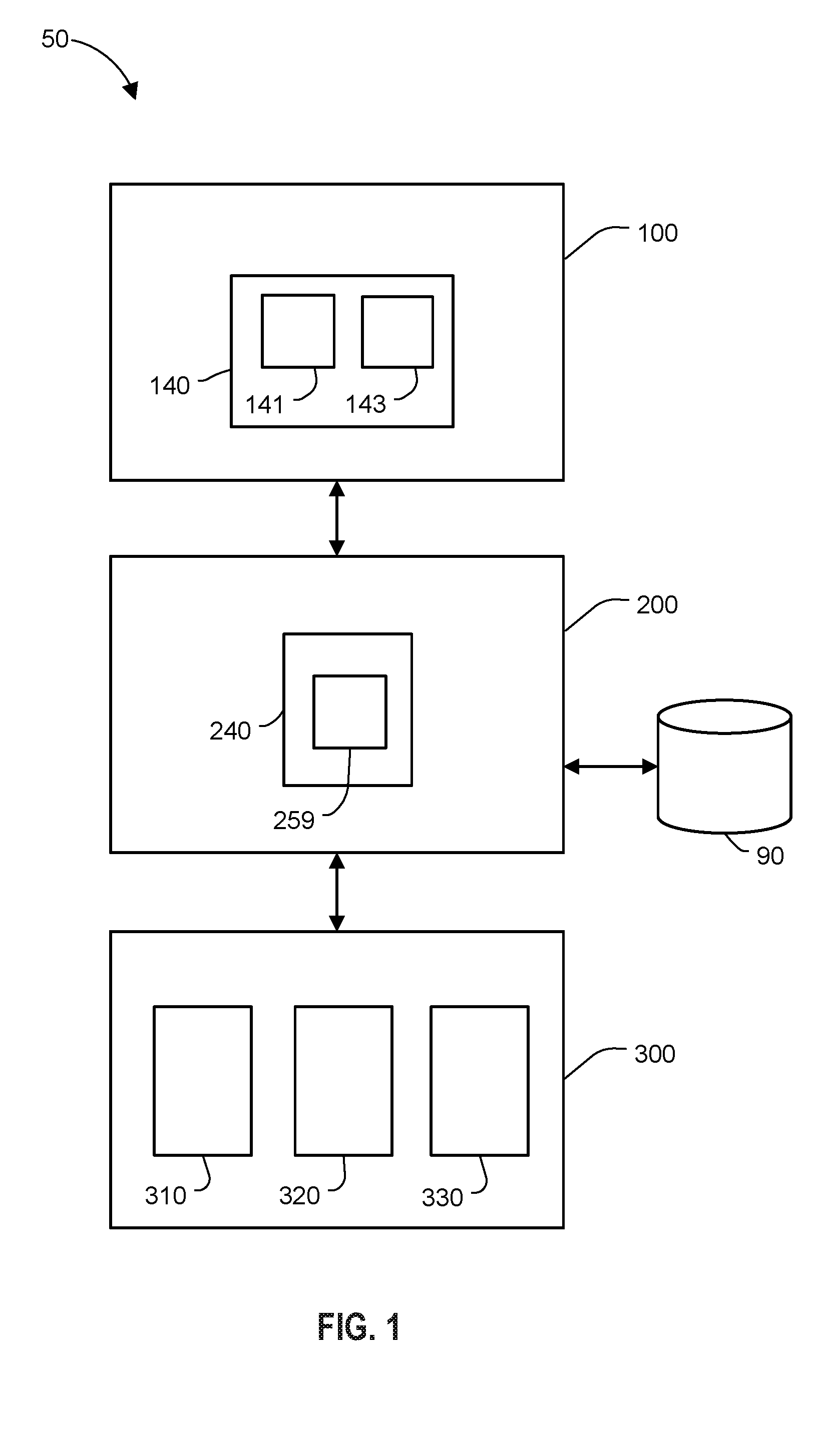
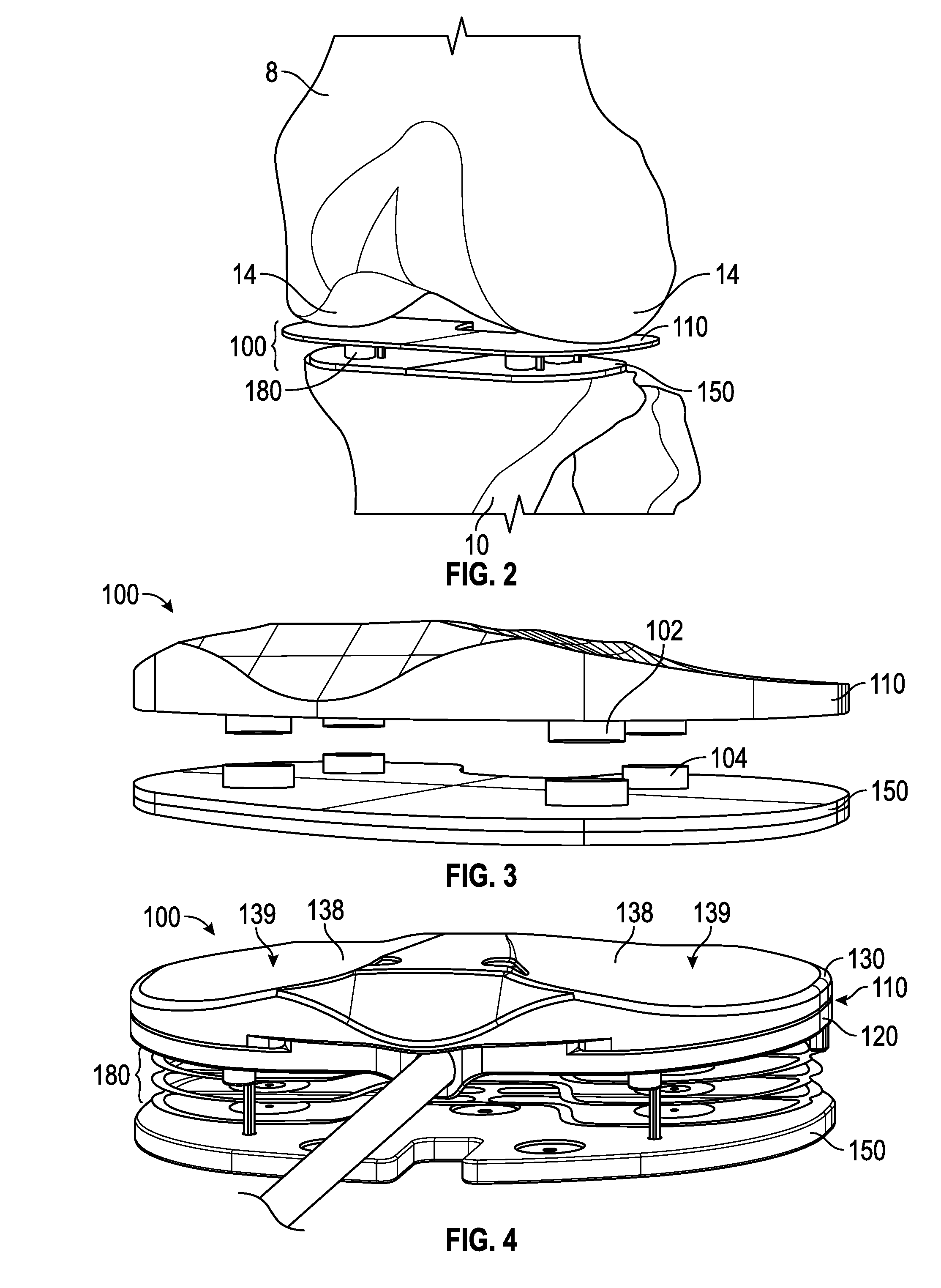
[0078]Disclosed herein are systems, devices, and methods for balancing a joint during surgical procedures on joints, such as prosthetic arthroplasty. FIG. 1 is a functional block diagram of a joint balancing system 50, according to one embodiment of the invention. Joint balancing system 50 may include a trial insert (“insert”) 100, a controller assembly 200, and a display system 300. The joint balancing system 50 includes an insert 100 with one or more plates, one or more sensors and at least one actuator / actuated mechanism for actuating the device against one or more parts of the joint as illustrated in FIGS. 2-11. The actuated mechanism may be fluid powered, such as by air, electromechanical, electromagnetic, mechanical, piezoelectric, or a combination thereof. Other actuated mechanisms may also be used. The one or more plates are disposed between bone structures which define the joint, such as the femur and the tibia in a knee joint. The one or more sensors may provide force, pos...


PUM


Abstract

A joint balancing insert with an actuated mechanism is for balancing a joint during a joint surgery is disclosed. The joint balancing insert includes a first plate, a second plate and an actuator there between. The second plate includes an integrated mounting portion for mounting a cutting block used to guide surgical cuts of the joint during the joint surgery. Various configurations of the integrated mounting portion may be implemented in the insert to provide for mounting various types of cutting blocks, such as cutting blocks for tibial cuts, femoral cuts, and distal femoral cuts.

Description

RELATED APPLICATION[0001]This application claims the benefit of U.S. provisional patent application Ser. No. 62 / 137,661 entitled “Balancing Device for Arthroplasty and Methods of Use,” filed on Mar. 24, 2015, which is hereby incorporated by reference.FIELD OF THE INVENTION[0002]Various embodiments described herein relate generally to devices and methods for balancing a joint during prosthetic arthroplasty, and to actuated positioning and sensing devices for positioning prosthetic components and balancing a joint during arthroplasty surgery.BACKGROUND[0003]Arthroplasty involves the repair of a joint by replacing one or more portions of the joint to eliminate pain and improve movement. For example, loss of cartilage or friction between bone surfaces can be treated by inserting an artificial joint, which includes one or more prostheses designed to replace bone surfaces and cartilage while also allowing for a range of movement similar to the original joint.[0004]Knee arthroplasty typica...

Claims


Application Information

Patent Timeline
IPC IPC(8): A61F2/46A61B17/15
CPCA61F2/4657A61B17/154A61F2002/4668A61F2002/4694A61F2002/4658A61B17/155A61B17/1764A61B2017/0268A61B17/025A61B2017/00022A61B2017/00557A61B2090/061A61B2090/065A61F2/38A61F2002/4666A61F2/461
Inventor D'LIMA, DARRYL D.COLWELL, CLIFFORD W.
Owner XPANDORTHO
Learn More