Electrical connector

a technology of electric connectors and connectors, applied in the direction of electrical apparatus, connection, coupling device connection, etc., can solve the problems of difficult to simplify the connection operation, reduce the amount of work as much as possible, and the moveable member becomes an obstacle, so as to facilitate the pulling out of the flat conductive member

Active Publication Date: 2016-09-15
HIROSE ELECTRIC GROUP
View PDF0 Cites 3 Cited by
  • Summary
  • Abstract
  • Description
  • Claims
  • Application Information

AI Technical Summary

Benefits of technology

[0027]In other words, even if the engaged portion is rotated to the close position, the engaged portion will not be dragged by the pressure receiving portion in a direction to be away from the passage-allowing space. Therefore, it is achievable to securely bring the passage-allowing space to the engaged portion, so as to let the engaged portion pass the passage-allowing space towards the pull-out direction, and thereby to easily pull out the flat conductive member.
[0028]According to the present invention, upon pulling out the flat conductive member, the pressure receiving portion of the movable member at the open position abuts against the engaged portion of the flat conductive member. With the abutting force, the movable member is rotated to the close position. During this rotation, the passage-allowing space of the movable member comes to on the path of the engaged portion of the flat conductive member over the whole area in the pull-out direction of the flat conductive member. At this point, the engaged portion passes the passage-allowing space backward, and thereby it is possible to pull out the flat conductive member. In addition, after pulling out, the movable member is continuously rotated and reaches the close position. As a result, an operator does not have to move the movable member back from the open position to the close position after pulling out the flat conductive member from the electrical connector.

Problems solved by technology

However, when the movable member stays being lifted at the open position, the movable member becomes an obstacle for connecting other electronic components on the circuit board, on which the conventional electrical connector is mounted.
When it is necessary to connect a large number of electronic components, it is necessary to rotate the movable member to the close position each time, thereby making it difficult to simplify the connection operation, and to reduce an amount of work as much as possible.

Method used


Image

  • Electrical connector
  • Electrical connector
  • Electrical connector

Examples


Embodiment Construction

[0036]Hereunder, an embodiment of the present invention will be described with reference to the accompanying drawings.

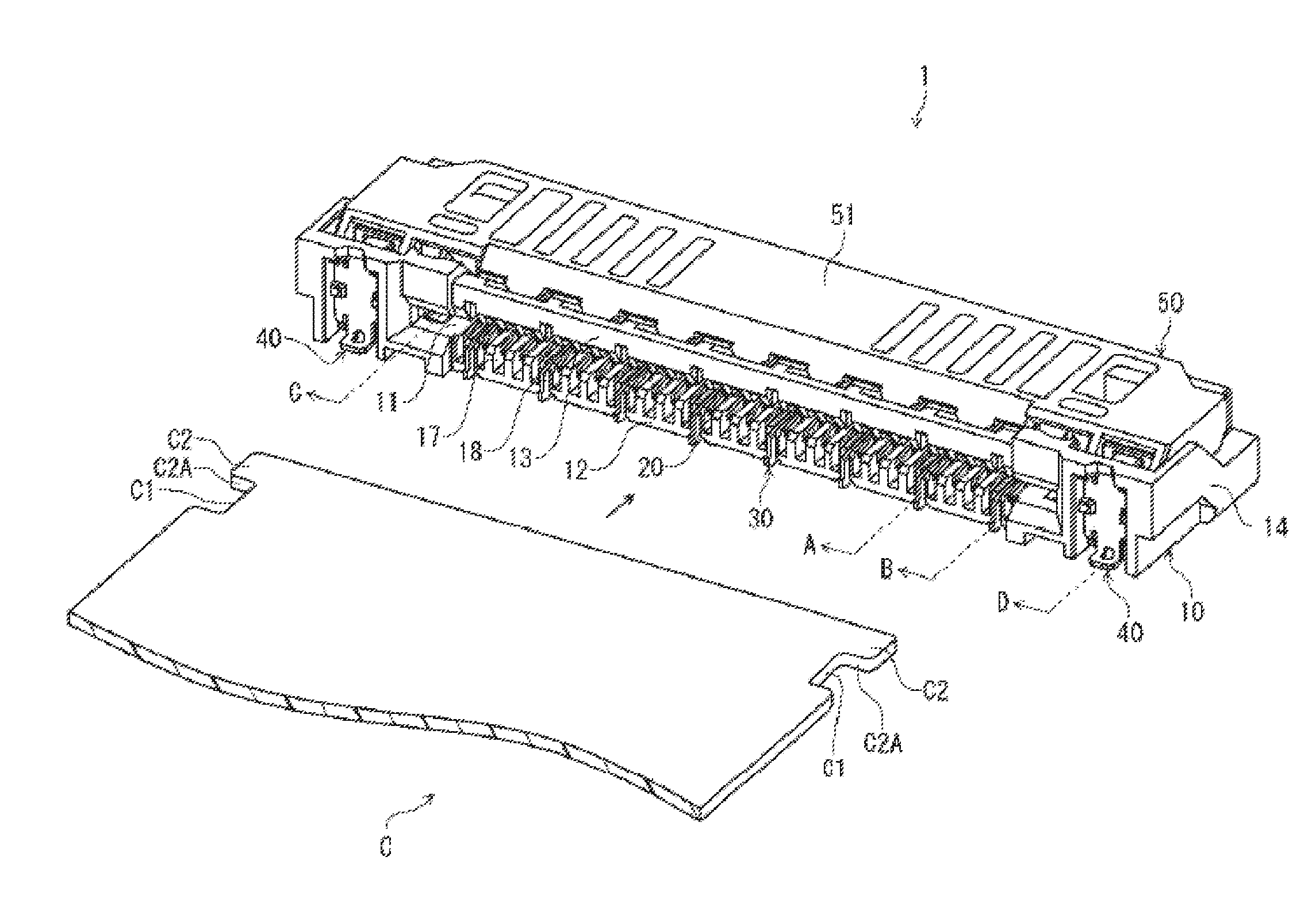
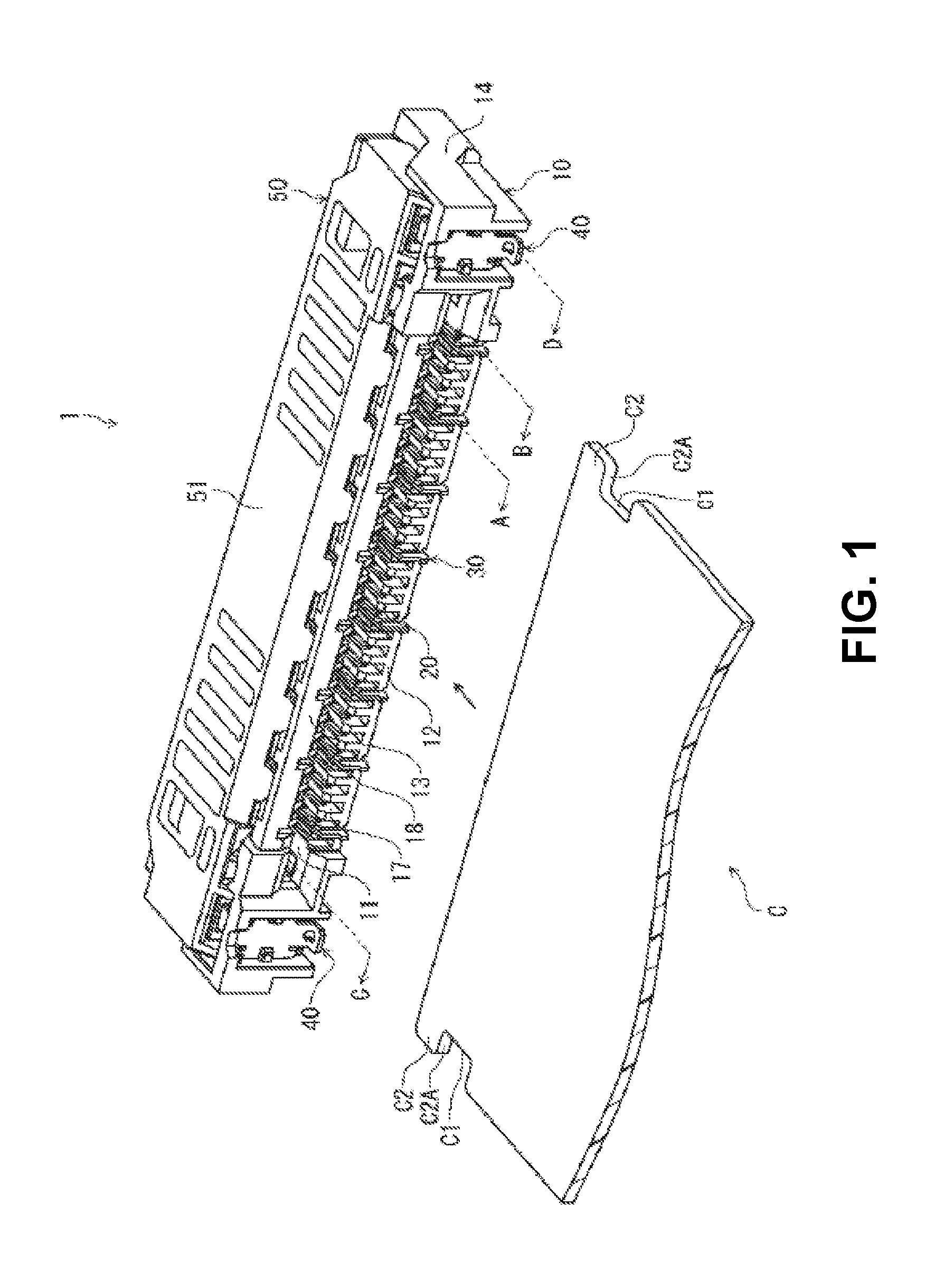
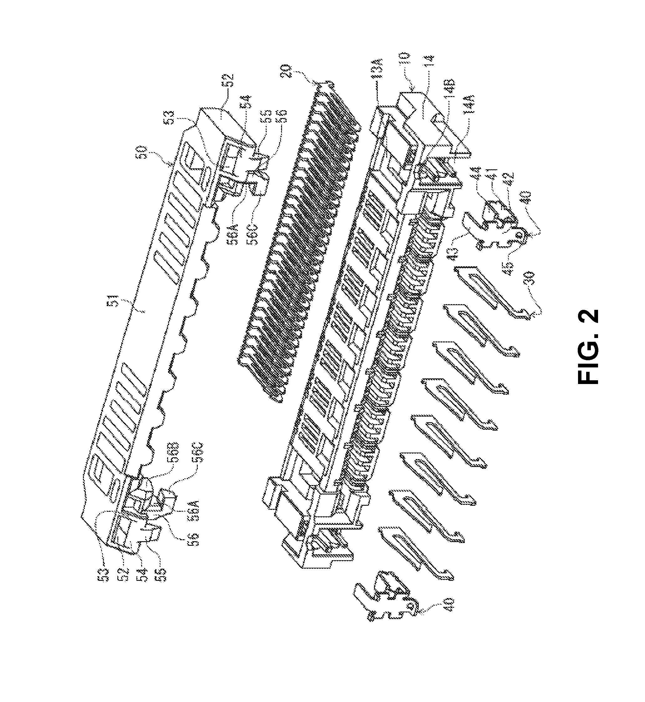
[0037]FIG. 1 is a perspective view showing an electrical connector 1 for a flat conductive member C (hereinafter, referred to as “connector 1”) and the flat conductive member C according to an embodiment of the present invention. FIG. 2 is an exploded view showing the connector 1.

[0038]FIGS. 3(A) through 3(D) are sectional views showing the electrical connector 1 before the flat conductive member C is inserted into the electrical connector 1 taken along a surface perpendicular to an arrangement direction of terminals of the electrical connector 1 according to the embodiment of the present invention. More specifically, FIG. 3(A) is a sectional view showing the electrical connector 1 taken at a signal terminal (along a line A in FIG. 1). FIG. 3(B) is a sectional view showing the electrical connector 1 taken at a ground terminal (along a line B in FIG. 1). FIG. 3(C) is ...


PUM


Abstract

An electrical connector is to be connected to a flat conductive member. The electrical connector includes a housing including a receiving portion for receiving the flat conductive member; terminals arranged in the housing in a terminal arrangement direction; and a movable member rotatable between an open position and a close position relative to the housing. The movable member includes an engaging portion for engaging an engaged portion when the movable member is situated at the close portion. The movable member includes a pressure receiving portion for abutting against the engaged portion when the movable member is situated at the open portion. The movable member includes a passing allowing space between the engaging portion and the pressure receiving portion for allowing the engaged portion to pass through. The engaged portion passes through the passing allowing space when the movable member is rotated toward the close position.

Description

BACKGROUND OF THE INVENTION AND RELATED ART STATEMENT[0001]The present invention relates to an electrical connector to be connected to a flat conductive member. More specifically, the present invention relates to an electrical connector to be mounted on a mounting surface of a flat conductive member such as a circuit board and the like, so that the electrical connector is connected to the flat conductive member.[0002]Patent Reference has disclosed a conventional electrical connector to be connected to a flat conductive member. The flat conductive member is inserted and pulled in a front-and-back direction, which is a direction horizontal to a mounting surface of a circuit board.[0003]The conventional electrical connector disclosed in Patent Reference includes a housing, a plurality of terminals, and a movable member (a shell). The housing extends along the mounting surface in a direction perpendicular to the front-and-back direction as a longitudinal direction thereof. The terminals...

Claims


Application Information

Patent Timeline
Patent Type & Authority Applications(United States)
IPC IPC(8): H01R12/72H01R13/639
CPCH01R13/639H01R12/721H01R12/51H01R13/629H01R13/633H01R12/79H01R12/87
Inventor TAMAKI, SHOICHIRO
Owner HIROSE ELECTRIC GROUP
Why Eureka
Try Eureka