
Condition based engine parts monitoring

a technology of engine parts and monitoring conditions, applied in the field of engine parts, can solve the problems of unsatisfactory engine maintenance events, undesirable maintenance events, undesirable maintenance events,

Active Publication Date: 2016-09-08
AI ALPINE US BIDCO INC
View PDF30 Cites 42 Cited by
  • Summary
  • Abstract
  • Description
  • Claims
  • Application Information

AI Technical Summary

Benefits of technology

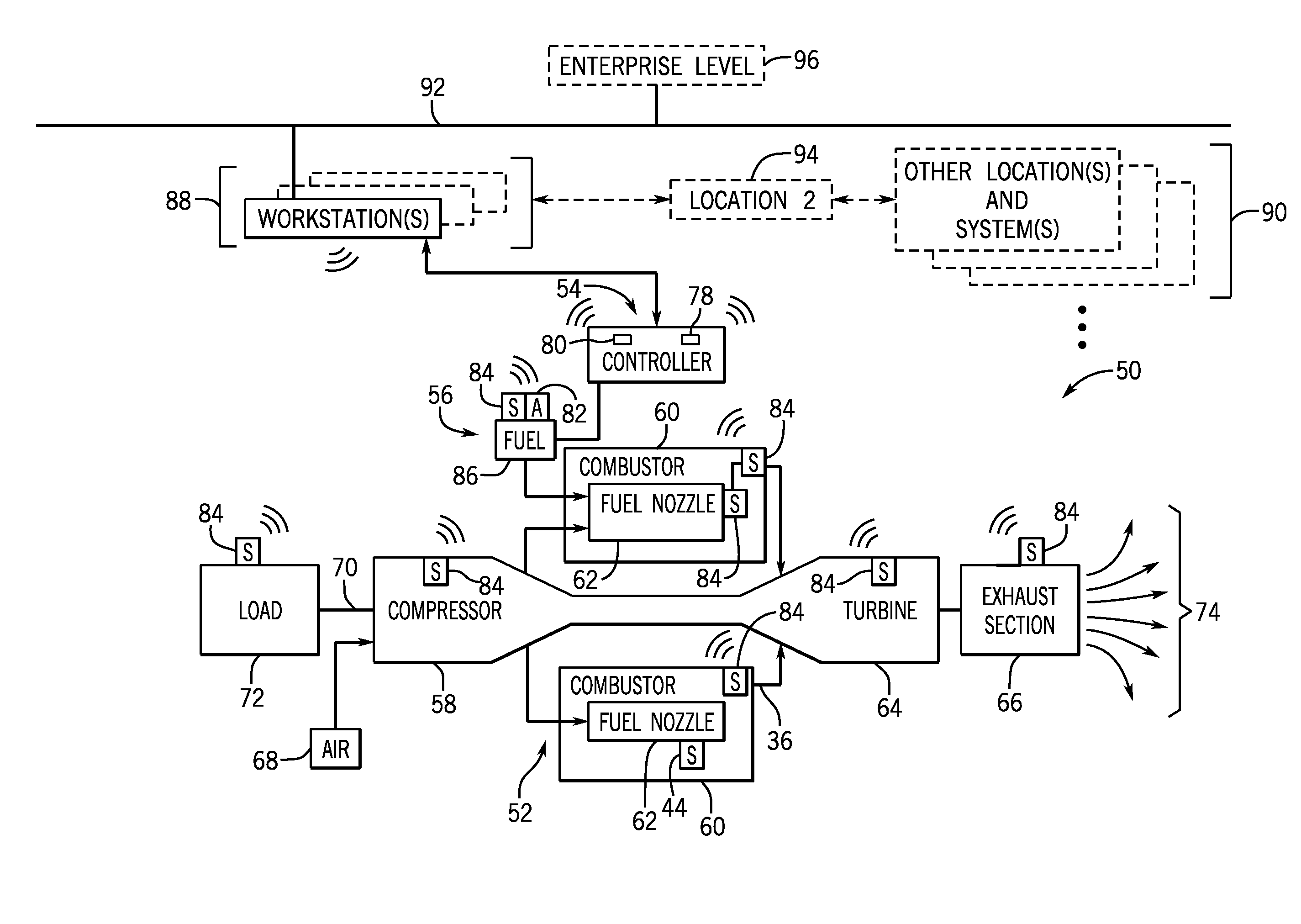
The invention is about a system and a device that use a wireless sensor to monitor the vibration of a machine part. The system or device initiates preventative actions when the vibration exceeds an acceptable threshold range. This invention helps to improve the efficiency and accuracy of identifying and addressing potential issues with machine parts.

Problems solved by technology

Moving parts in engines that develop one or more cracks may lead to an undesirable maintenance event of the engines if the crack goes undetected.
For example, an undetected cracked turbine blade in a gas turbine engine may release from its holding disk, thereby potentially causing an undesirable maintenance event.
In addition, an undetected cracked connecting rod in a reciprocating internal combustion engine could break apart and be released from its cap, thereby potentially causing an undesirable maintenance event.
This may waste resources by replacing a movable part that may have a substantial remaining useful life.
Also, schedule based monitoring may not catch a movable part that is cracked in time before it causes an undesirable maintenance event.
The wires on sensors attached to moving parts may become tangled as the engine operates, which may lead to the wires disconnecting from the sensor and / or the controller.

Method used


Image

  • Condition based engine parts monitoring
  • Condition based engine parts monitoring
  • Condition based engine parts monitoring

Examples


Embodiment Construction

[0014]One or more specific embodiments of the present disclosure will be described below. In an effort to provide a concise description of these embodiments, all features of an actual implementation may not be described in the specification. It should be appreciated that in the development of any such actual implementation, as in any engineering or design project, numerous implementation-specific decisions must be made to achieve the developers' specific goals, such as compliance with system-related and business-related constraints, which may vary from one implementation to another. Moreover, it should be appreciated that such a development effort might be complex and time consuming, but would nevertheless be a routine undertaking of design, fabrication, and manufacture for those of ordinary skill having the benefit of this disclosure.

[0015]When introducing elements of various embodiments of the present disclosure, the articles “a,”“an,”“the,” and “said” are intended to mean that th...


PUM


Abstract

Condition based engine parts (e.g., movable engine parts) monitoring is disclosed. The techniques may enable detecting cracks present in engine parts while the engine is operational. In one embodiment, a system includes a wireless sensor configured to be disposed on a movable part internal to a machine and communicate wirelessly and a controller that includes a processor. The processor may be configured to initiate communication with the wireless sensor by receiving a wireless signal indicative of a frequency of vibration of the internal movable part from the wireless sensor, to obtain an acceptable threshold range of vibrations for the internal movable part from one or more data sources, to determine whether the frequency of vibration is within the acceptable threshold range of vibrations for the internal movable part, and to initiate preventative actions when the frequency is not within the acceptable threshold range.

Description

BACKGROUND[0001]The subject matter disclosed herein relates to engine parts (e.g., movable engine parts) monitoring and, more specifically, to techniques to detect conditions, such as cracks, on operational parts of engines in real-time.[0002]Moving parts in engines that develop one or more cracks may lead to an undesirable maintenance event of the engines if the crack goes undetected. For example, an undetected cracked turbine blade in a gas turbine engine may release from its holding disk, thereby potentially causing an undesirable maintenance event. In addition, an undetected cracked connecting rod in a reciprocating internal combustion engine could break apart and be released from its cap, thereby potentially causing an undesirable maintenance event.[0003]Oftentimes, to inhibit the potential consequences of operating an engine with cracked movable parts, operators use schedule based monitoring of movable parts included in engines. Schedule based monitoring may refer to replacing...

Claims


Application Information

Patent Timeline
IPC IPC(8): G01M5/00G01M15/14G01N29/24G01N29/04G01N29/44
CPCG01M5/0066G01N29/04G01N2291/269G01N29/2437G01M15/14G01N29/44G01M15/12G01N19/08G01M13/028
Inventor RAMAN, VENKATESHNANDIGAMA, PAVAN CHAKRAVARTHY
Owner AI ALPINE US BIDCO INC
Learn More