
Optical displacement sensor

a technology of optical displacement sensor and optical polarization sensor, which is applied in the direction of converting sensor output optically, photoelectric exposure meters, instruments, etc., can solve the problems of not providing actual measurement value and no actual measurement value, and achieve the effect of maximum brightness in the pixel, easy measurement and convenient measuremen

Active Publication Date: 2016-09-01
SICK OPTEX
View PDF1 Cites 1 Cited by
  • Summary
  • Abstract
  • Description
  • Claims
  • Application Information

AI Technical Summary

Benefits of technology

The present invention provides an optical displacement sensor that can accurately measure the distance to an object even when the light reflecting level changes dramatically. The sensor calculates the exposure time and measures the actual distance to the object based on this exposure time. This ensures that the measurement value is accurate and free from any measurement error caused by changes in the light reflecting level. The sensor also monitors the light receiving level of the pixels in the imager and stops the exposure when the light level reaches a preset level, resulting in a proper image without overexposure or underexposure. Additionally, the sensor can measure the actual distance value by either validating or reducing the calculated measurement distance based on the difference between the measured exposure time and the previous value. This ensures that the actual measurement value is accurate and the measurement response time is sped up.

Problems solved by technology

It has, however, been found that the above discussed conventional technology has a problem that, although measurement is possible when the light reflecting level of the object is high, no actual measurement value can be provided as a result of increase in measurement error.
As a result thereof, unlike the image shot during the usual time, measurement takes place with the background of the high light reflectance and, therefore, a measurement error is brought about due to that influence and the actual measurement value is not provided.
Also, it may occur that the measurement error under the influence of ambient light around the object to be measured may result in.

Method used


Image

  • Optical displacement sensor
  • Optical displacement sensor
  • Optical displacement sensor

Examples


Embodiment Construction

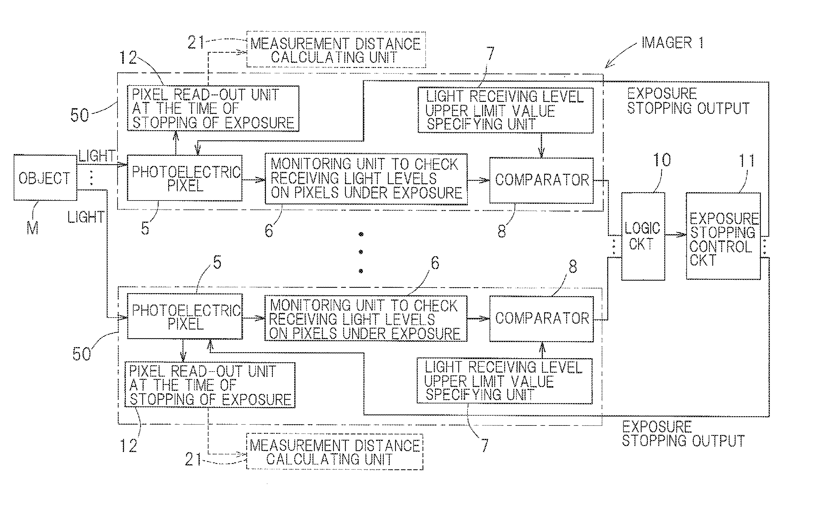
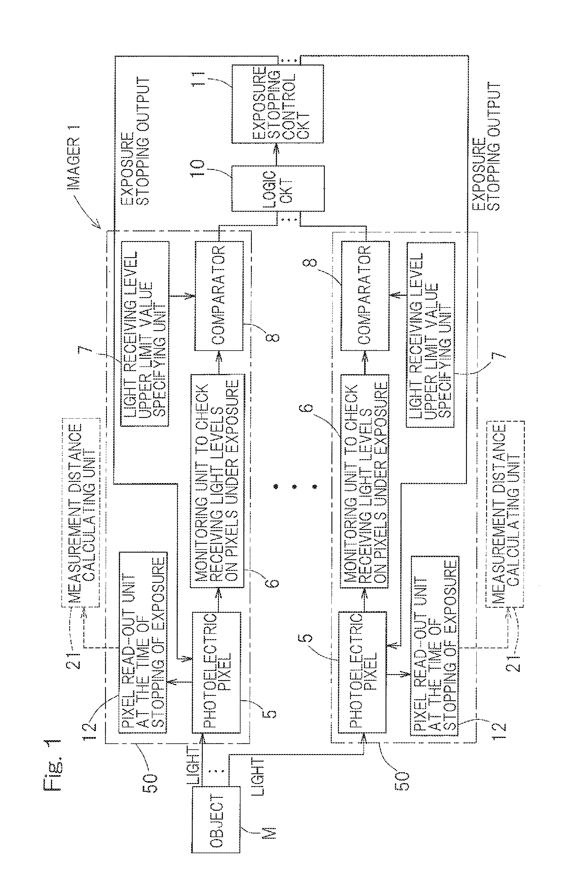
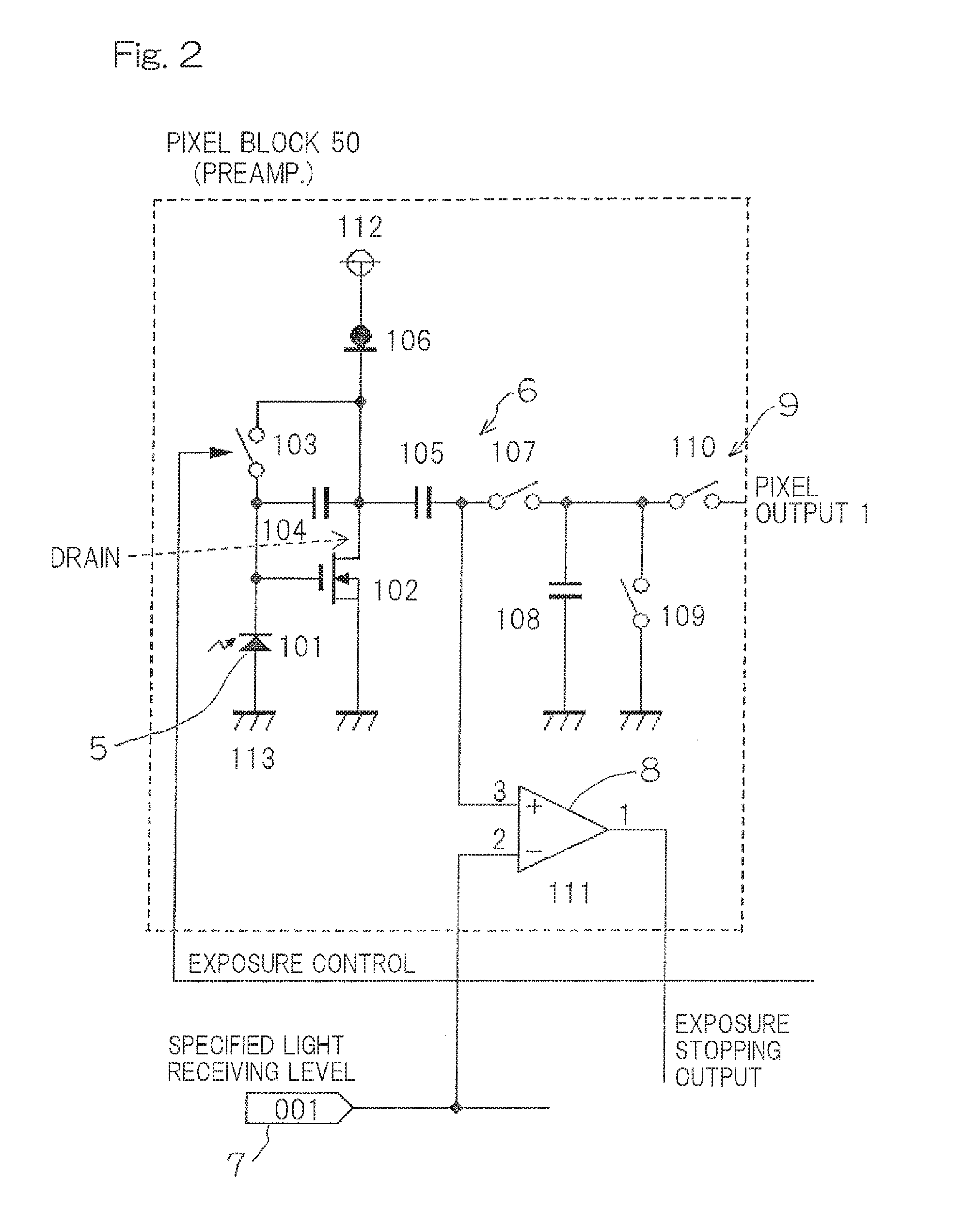
[0032]Hereinafter, a preferred embodiments of the present invention will be described in detail with particular reference to the accompanying drawings. In particular, FIG. 1 is a block diagram showing an imager 1 having an automatic exposure stopping function, which pixel is contained in an optical displacement sensor designed in accordance with the preferred embodiment of the present invention. This imager 1 has pixel blocks 50. Each of the pixel blocks 50 includes a group of pixels 5, which is comprised of multiple pixels for receiving light from an object M and also includes a light receiving level monitoring unit 6 for monitoring a light receiving level of each of the pixels 5 under exposure; a light receiving level upper limit value specifying unit 7 for specifying the light receiving level upper limit value of each of the pixels 5; multiple comparators 8 each operable to compare the light receiving level of the respective pixel 5 during the exposure with the upper limit value ...


PUM


Abstract

The present invention includes an imager 1 having an automatic exposure stopping function, which are implemented therein, and includes an exposure time measuring unit 24 to measure the exposure time from the start of exposure to the stopping of exposure in the imager 1, a measurement distance calculating unit 21 to calculate the measurement distance to an object M on the basis of a displacement of the light receiving position in the imager 1, and a data output / storage unit 25 to output and / or store, as data related with acquisition of a distance actual value, which is an actual distance to the object, in a condition in which the measured exposure time and the measurement distance calculated with this exposure time are associated with each other.

Description

CROSS REFERENCE TO THE RELATED APPLICATION[0001]This application is based on and claims Convention priority to Japanese patent application No. 2015-036754, filed Feb. 26, 2015, the entire disclosure of which is herein incorporated by reference as a part of this application.BACKGROUND OF THE INVENTION[0002]1. Field of the Invention[0003]The present invention relates to an optical displacement sensor equipped with an imager having an automatic exposure stopping function of automatically stopping the exposure of a pixel receiving the light.[0004]2. Description of Related Art[0005]The automatic exposure function currently implemented in the conventional imaging device is so designed as to set the exposure time for the subsequent shooting by performing such a calculation as that of the average brightness of the entire pixels or the average brightness of specific pixels through processing of an image that has been shot and depending on difference between the calculation result and a targe...

Claims


Application Information

Patent Timeline
Patent Type & Authority Applications(United States)
IPC IPC(8): G01D5/34G01J1/42H04N23/75
CPCG01J1/4209G01D5/34G01B11/14H04N25/706
Inventor YUGUCHI, TASUKU
Owner SICK OPTEX
Learn More