Battery rod assembly, electronic cigarette, and electronic cigarette charging apparatus
a battery rod and charging device technology, applied in the field of daily electronic products, can solve the problems of electronic cigarette damage, the method of threaded connection tends to need a plurality of rotations, etc., and achieve the effect of avoiding unstable charge, simple and effective, and stable and proper connection
- Summary
- Abstract
- Description
- Claims
- Application Information
AI Technical Summary
Benefits of technology
Problems solved by technology
Method used
Image
Examples
first embodiment
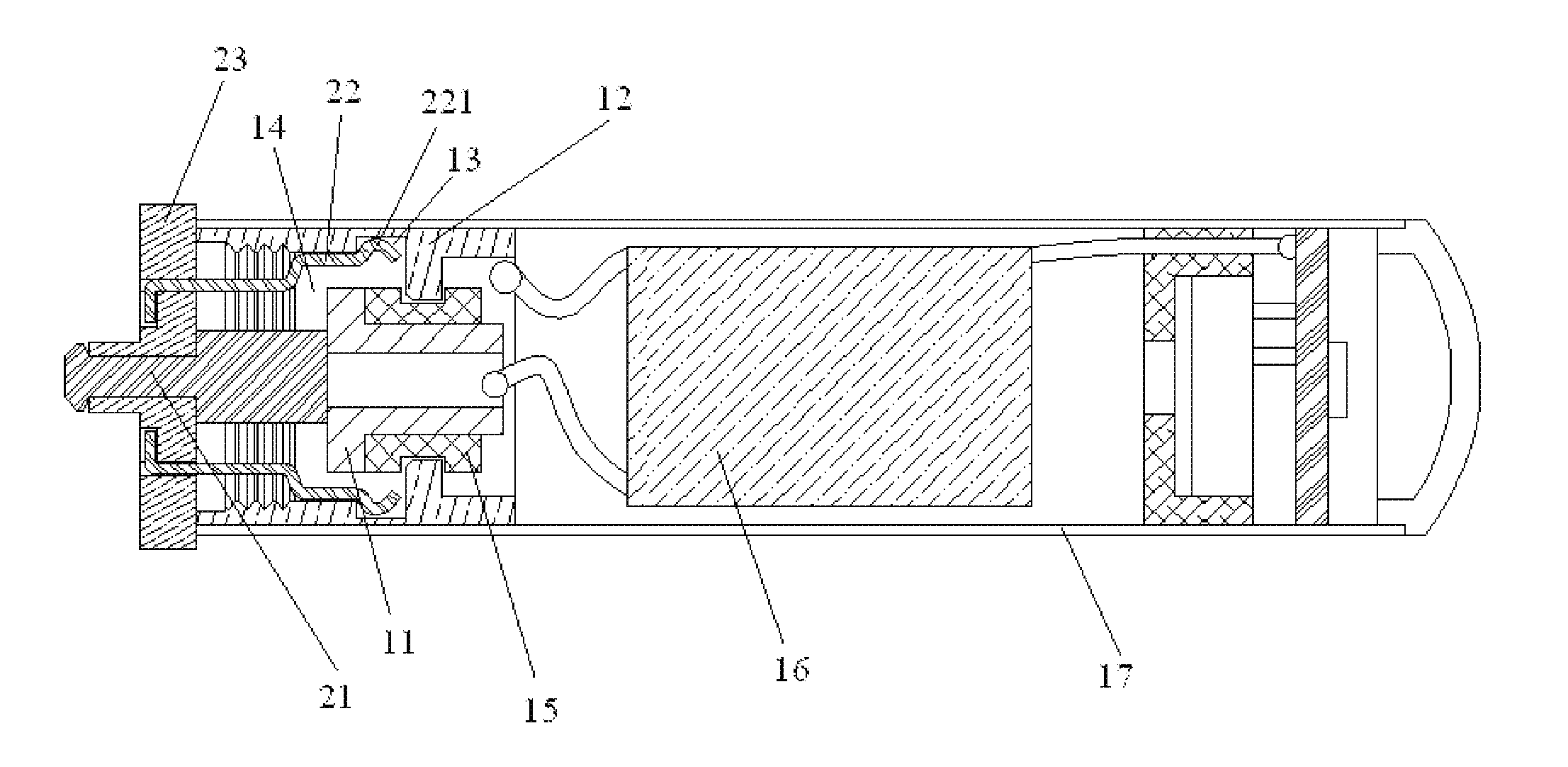
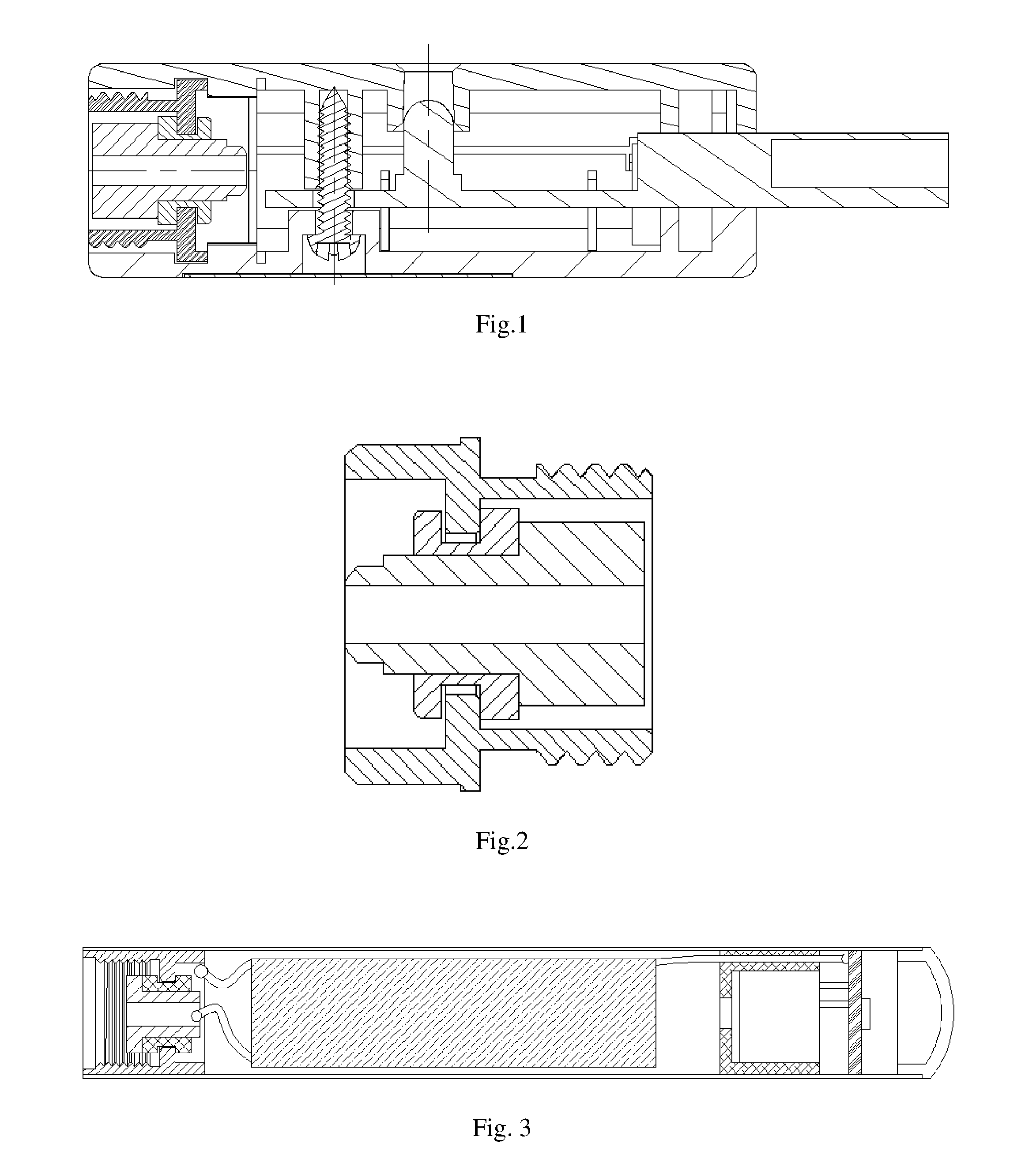
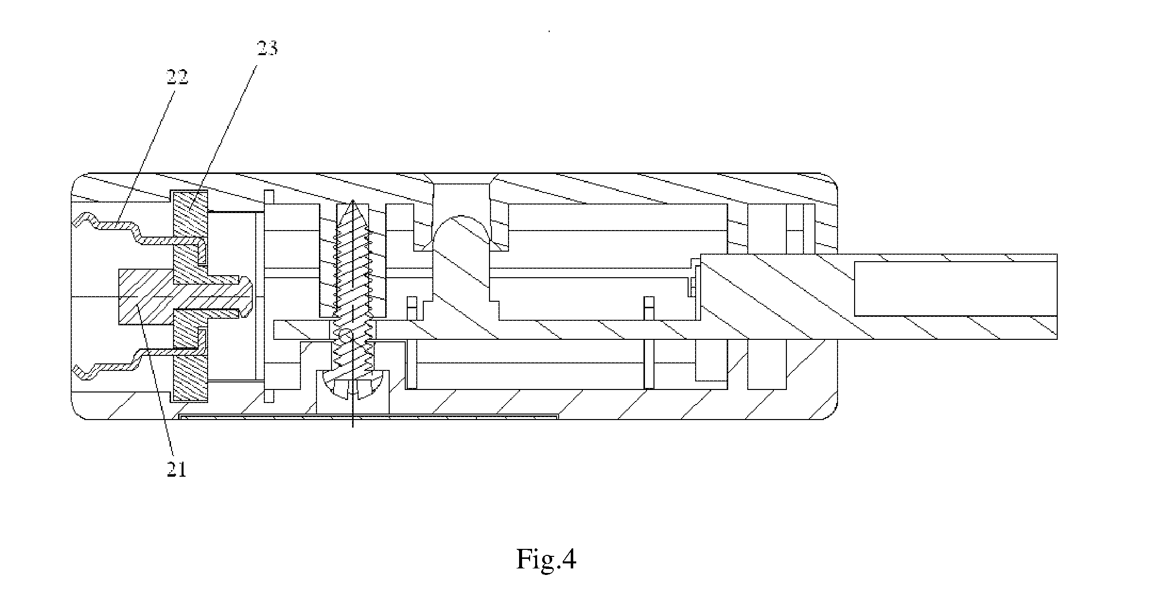
[0044]In the first embodiment, a first through hole is defined on the electrode support 23, and the first charging electrode 21 is capable of being inserted and fixed in the first through hole. Preferably, the first through hole is located in the circle center of the electrode support 23. The first charging electrode 21 can be made from conductive materials such as flexible conductive rubber or silicone gel etc, or the first charging electrode 21 can be fixed on the electrode support 23 via elastic components so that it can elastically and telescopically move along an axial direction thereof. The first charging electrode 21 includes an electrode body 213, a first charging projection 211 and a first charging buckle 212. The first charging projection 211 and the first charging buckle 212 are formed by oppositely extending from two ends of the electrode body 213; and a diameter of the first charging projection 211 and that of the first charging buckle 212 are both larger than a diamete...
second embodiment
[0046]In the second embodiment, in order to ensure a more convenient electrical connection between the first charging electrode 21 and other circuit structures in the charging apparatus main body and simplify circuit layouts, an annular flange 231 is provided on an end surface of the electrode support 23 that is close to the charging apparatus main body and extends along a periphery of the first through hole. The annular flange 231 extends from the end surface towards the direction close to the charging apparatus main body. The first charging electrode 21 includes of an electrode body 213, a first charging projection 211 and a first charging buckle 212. The first charging projection 211 and the first charging buckle 212 are formed by oppositely extending from two ends of the electrode body 213; and a diameter of the first charging projection 211 and that of the first charging buckle 212 are both larger than a diameter of the electrode body 213. The first through hole runs through t...
third embodiment
[0047]In the third embodiment, the first charging electrode 21 is fixed on the electrode support 23 in any one mode above, while the second charging electrode 22 is fixed in the fixing groove of the electrode support 23. The second charging electrode 22 includes a buckling bending portion 221, a connecting portion 223 and a fixing portion 224 which is utilized to fix the second charging electrode 22 on the electrode support 23. The bucking bending portion 221 is arranged on one end of the connecting portion 223 that is away from the fixing portion 224, or arranged in the middle of the connecting portion 223. The fixing portion 224 is completely inserted and fixed in the fixing groove of the electrode support 23. Preferably, as shown in FIG. 5, the fixing portion 224 is also provided with a fixed bending portion 225 at one end away from the connection portion 223. The fixed bending portion 225 is arranged at an angle to the fixing portion 224, and the angle is an acute angle, a righ...
PUM
| Property | Measurement | Unit |
|---|---|---|
| angle | aaaaa | aaaaa |
| diameter | aaaaa | aaaaa |
| shapes | aaaaa | aaaaa |
Abstract
Description
Claims
Application Information
 - R&D
- Intellectual Property
- Life Sciences
- Materials
- Tech Scout
- Unparalleled Data Quality
- Higher Quality Content
- 60% Fewer Hallucinations
Browse by: Latest US Patents, China's latest patents, Technical Efficacy Thesaurus, Application Domain, Technology Topic, Popular Technical Reports.
© 2025 PatSnap. All rights reserved.Legal|Privacy policy|Modern Slavery Act Transparency Statement|Sitemap|About US| Contact US: help@patsnap.com


