
Memory controller and associated control method

a memory controller and controller technology, applied in the field of memory, can solve the problems of delaying the execution period, degrading the read/write operation performance of the memory, and the efficiency of the fms method is usually limited, so as to simplify the control design of the memory and optimize the operation performan

Inactive Publication Date: 2016-08-11
REALTEK SEMICON CORP
View PDF8 Cites 7 Cited by
  • Summary
  • Abstract
  • Description
  • Claims
  • Application Information

AI Technical Summary

Benefits of technology

This patent is about a new controller for a type of memory called SDRAM. The goal is to make it easier to control and improve how well the memory works. The new controller aims to solve problems in the current design.

Problems solved by technology

The efficiency of the FMS method is usually limited, however, so the frequency of an executing command cannot be elevated, which delays the executing period.
This may degrade the read / write operation performance of the memory.
The disadvantage is that the control is complex, which increases design difficulty, and the design cost of hardware is thus increased.

Method used


Image

  • Memory controller and associated control method
  • Memory controller and associated control method
  • Memory controller and associated control method

Examples


Embodiment Construction

[0017]Certain terms are used throughout the description and following claims to refer to particular components. As one skilled in the art will appreciate, manufacturers may refer to a component by different names. This document does not intend to distinguish between components that differ in name but not function. In the following description and in the claims, the terms “include” and “comprise” are used in an open-ended fashion, and thus should not be interpreted as a close-ended term such as “consist of”. Also, the term “couple” is intended to mean either an indirect or direct electrical connection. Accordingly, if one device is coupled to another device, that connection may be through a direct electrical connection, or through an indirect electrical connection via other devices and connections.

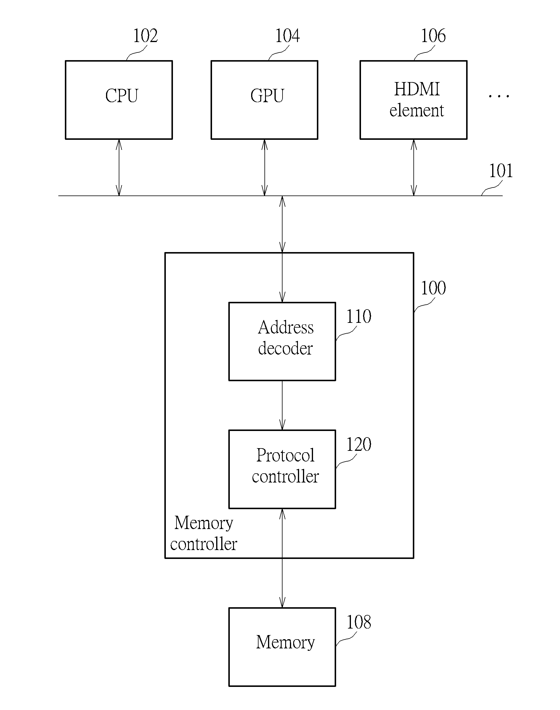
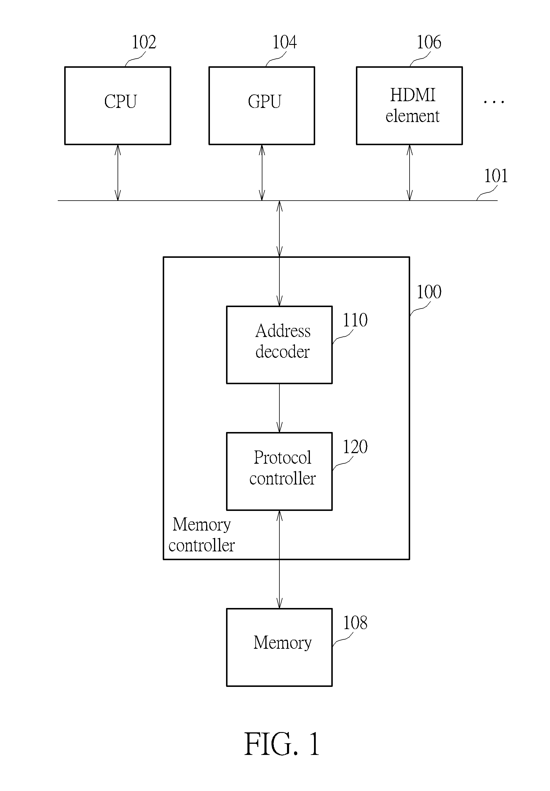
[0018]FIG. 1 is a diagram illustrating a memory controller 100 according to an embodiment of the present invention. As shown in FIG. 1, the memory controller 100 is coupled to the memory 10...


PUM


Abstract

A memory controller includes an address decoder and a protocol controller, where the address decoder is arranged for decoding a received signal to generate a plurality of command signals, where the plurality of signals are for accessing a plurality of banks of the memory and the protocol controller is arranged for re-scheduling an executing order of the plurality of command signals according to opening banks and pages, and for accessing the memory according to the plurality of command signals.

Description

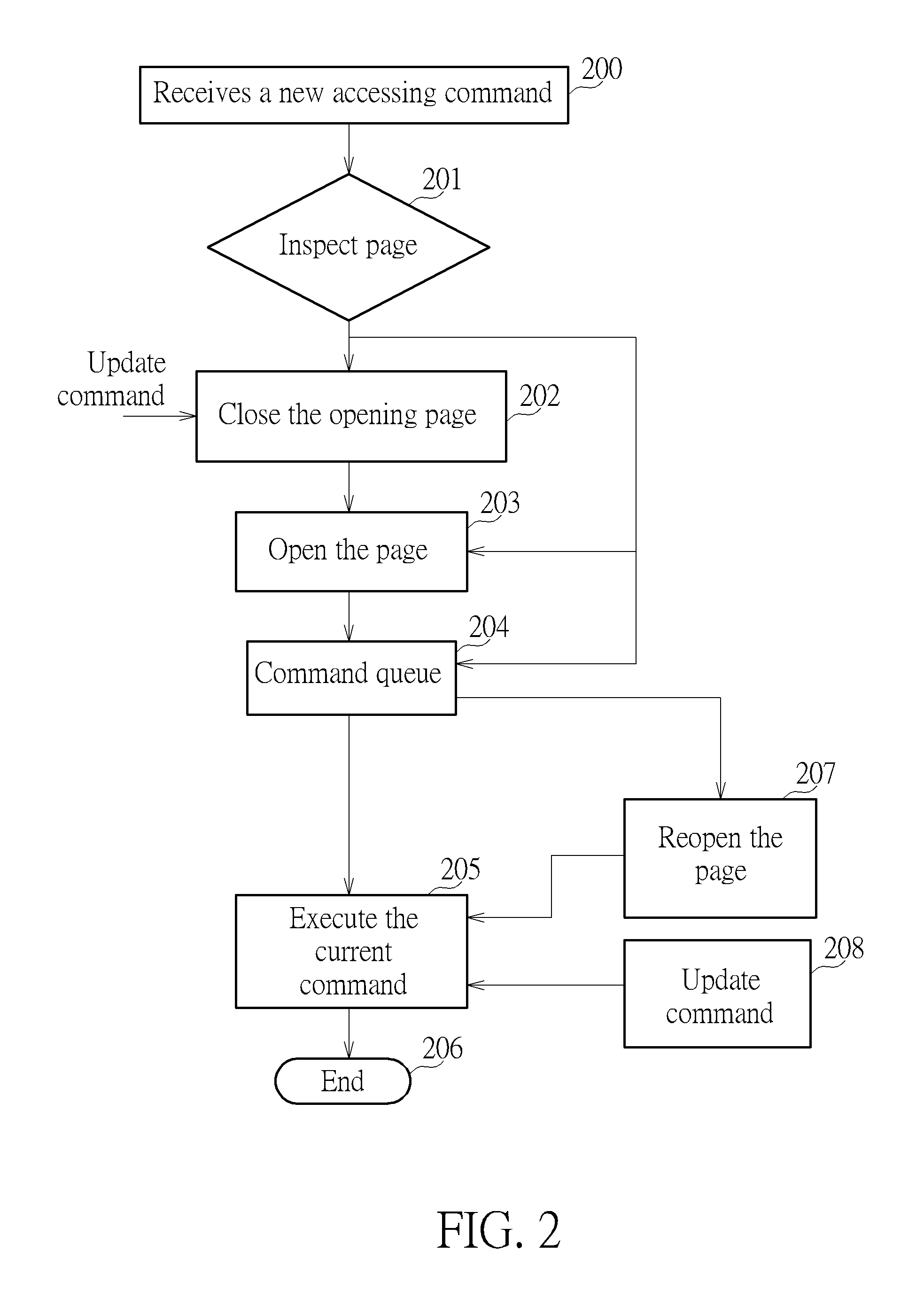
BACKGROUND OF THE INVENTION[0001]1. Field of the Invention[0002]The present invention relates to a memory, and more particularly, to a Dynamic Random-Access Memory (DRAM) controller and an associated control method.[0003]2. Description of the Prior Art[0004]In Synchronous Dynamic Random-Access Memory (SDRAM), a read / write data procedure comprises the following actions: (1) if the non-active page of the corresponding bank is not set, an active command needs to be sent for opening the specific non-active page of the corresponding accessed bank; (2) if the active page of the corresponding bank is set, a read / write operation can be executed directly when there is a page hit; in the case of a page miss, a precharge command needs to be sent to close the current corresponding page, and then an active command must be sent to set the page which is going to be read / written, and a read / write command must be sent for performing data read / write; and (3) an auto-refresh / refresh command needs to b...

Claims


Application Information

Patent Timeline
Patent Type & Authority Applications(United States)
IPC IPC(8): G06F3/06
CPCG06F3/0611G06F3/0673G06F3/0659G06F13/1631G06F13/16
Inventor CHANG, YA-MIN
Owner REALTEK SEMICON CORP
Learn More