
Eureka
For R&D, Eureka makes reading and utilizing patents & technical documents easy.
Eureka AIR
Designed for self-driven R&D workflows. Generate viable solutions, solve complex R&D challenges, empower your innovation with AI.

Eureka Materials
Designed for material experts only. Revolutionize your material R&D, from search, analyze, to developing new materials.

TechResearch
Generate reliable direction feasibility study reports for your R&D in just a few steps.

TechSeek
Discover and master advanced knowledge NOW. Basics, ideas, possibilities, all at once.

TechMind
As an expert in R&D Theories, TechMind can generates customized viable solutions instantly.

TechRisk
Analyze your overall solution with one click, know your potential R&D risks in advance.

TechMonitor
Get weekly tech updates, stay abreast of the latest tech innovations and key insights.
Brewing filter
- Summary
- Abstract
- Description
- Claims
- Application Information
AI Technical Summary
Benefits of technology
Problems solved by technology
Method used
Image

Examples
first embodiment
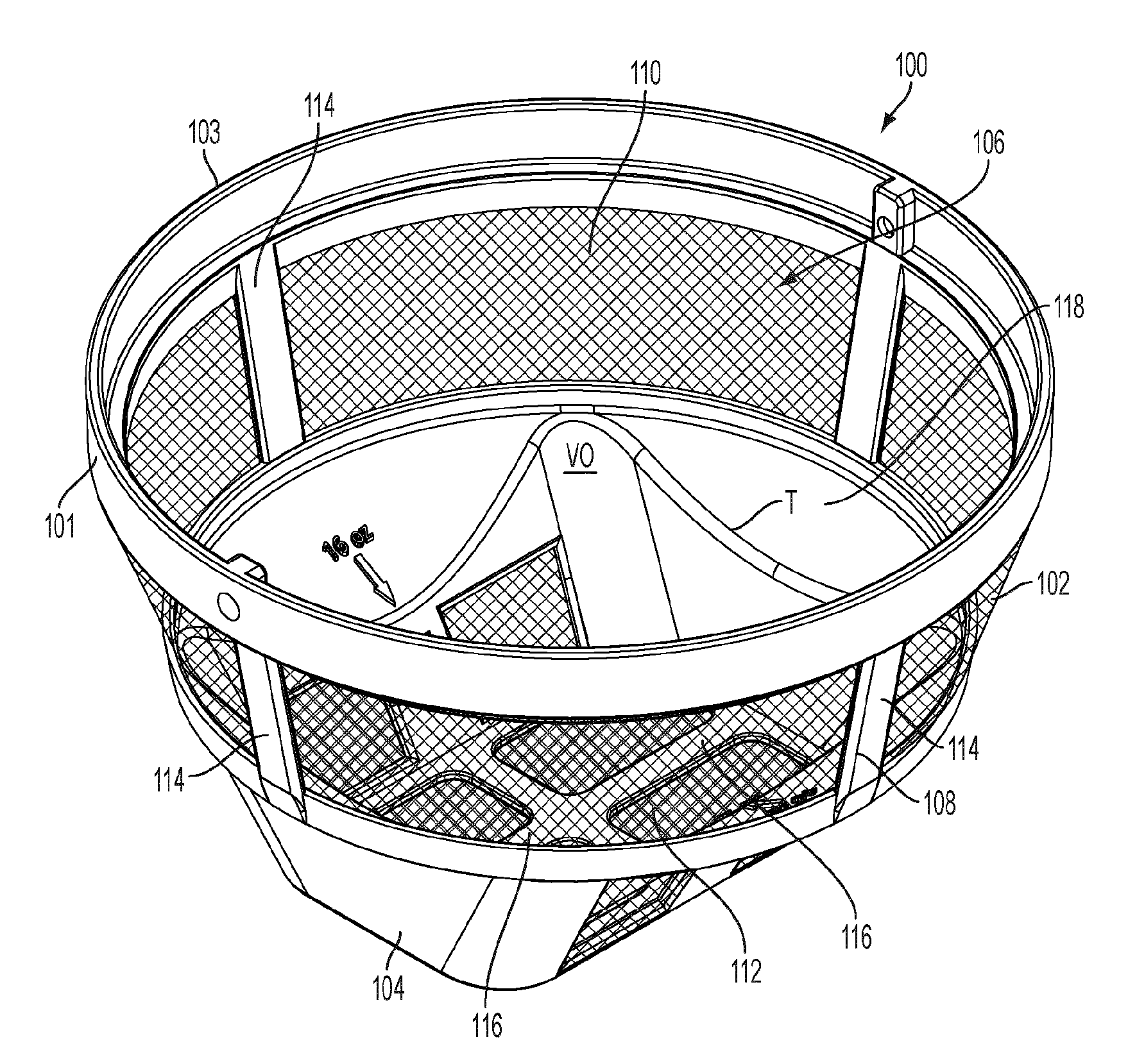
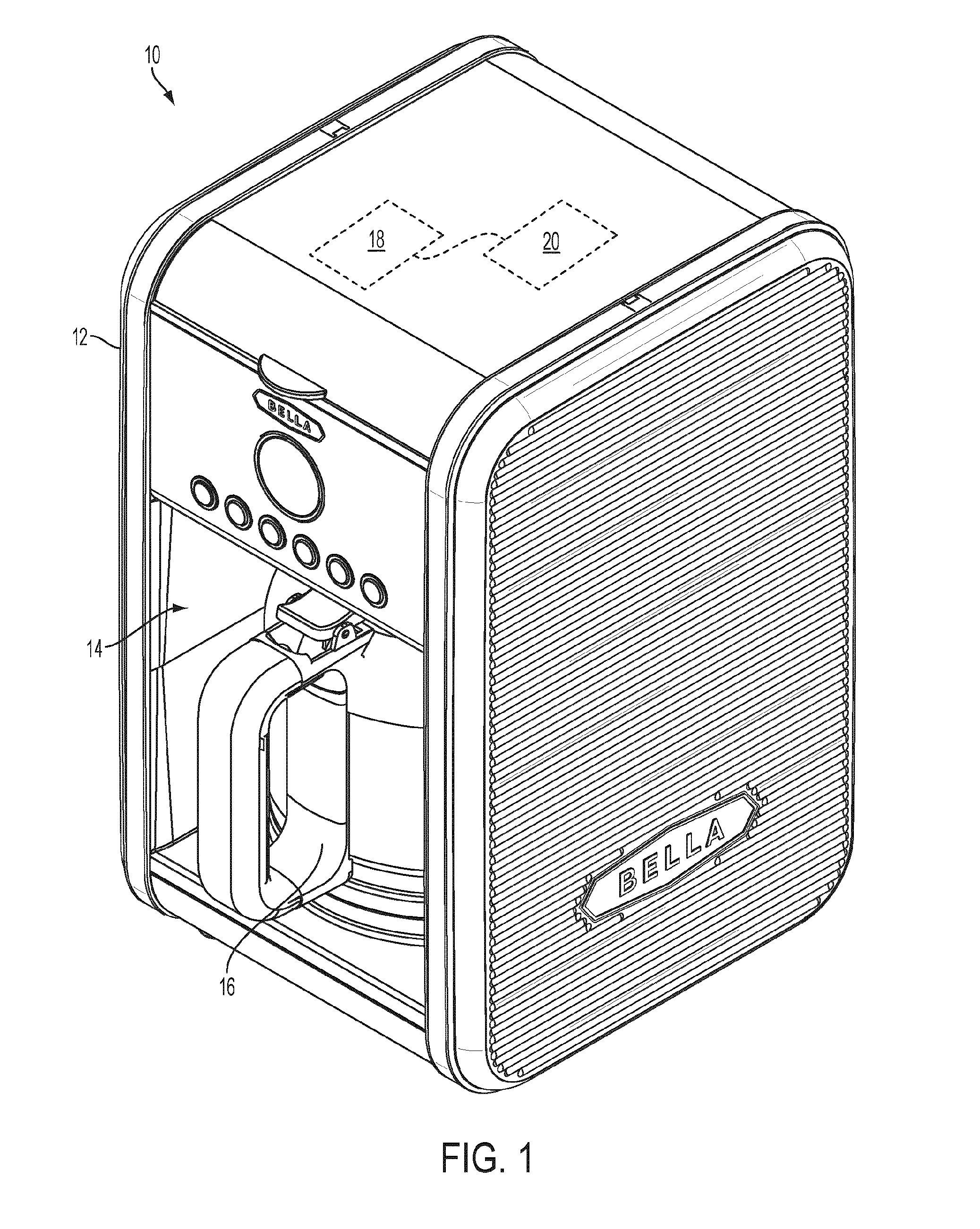
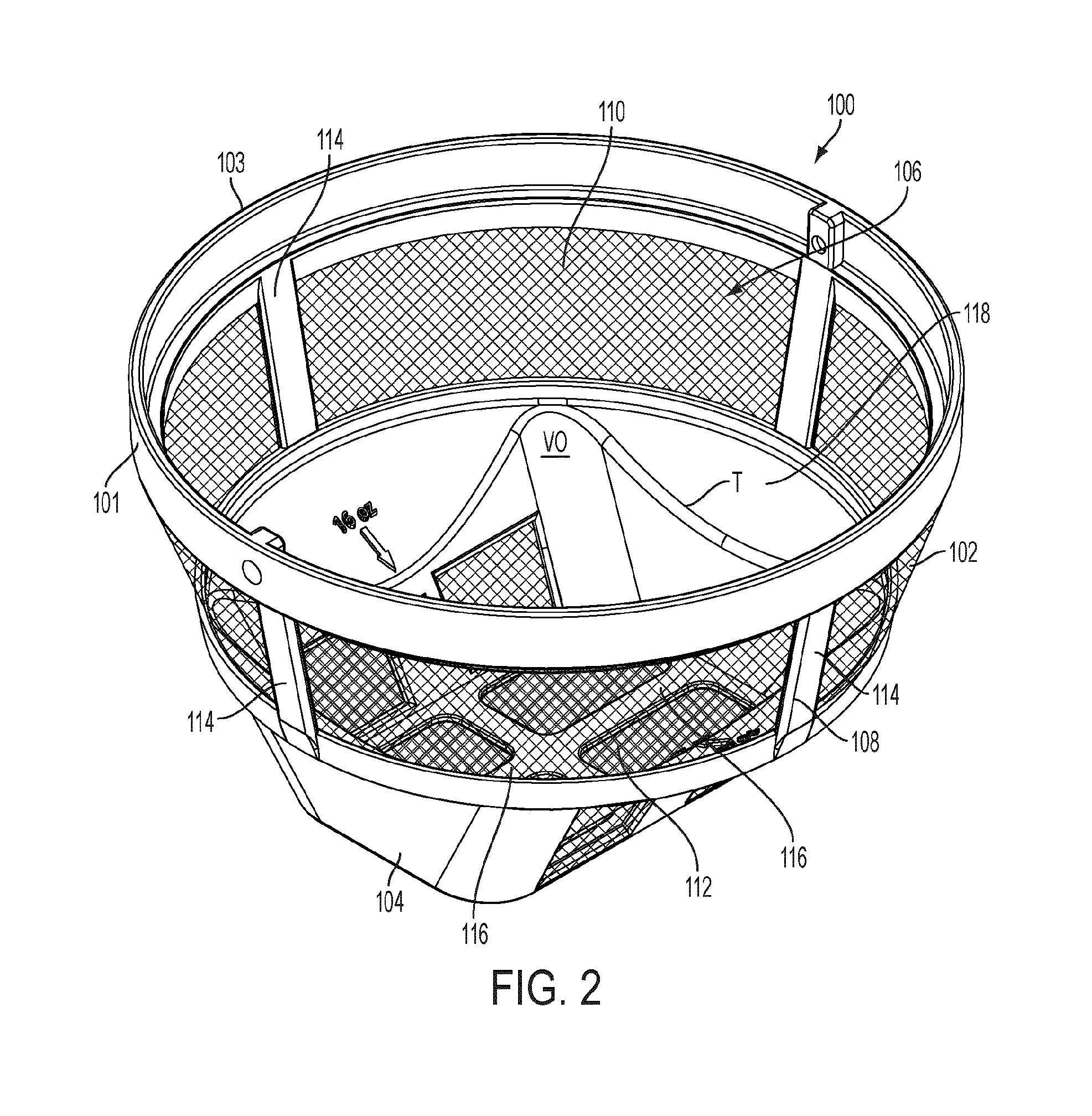
[0021]Referring to FIGS. 2 to 4, a filter 100 for the drip coffee machine 10 will be described. The filter 100 may be removable from the drip coffee machine 10.
[0022]The filter 100 includes a hollow, substantially funnel-shaped body 101. The body 101 generally includes a top portion 102 having an open top end 103, and a bottom portion 104 having a closed bottom end 105 (shown in FIG. 4). When the filter 100 is disposed in the coffee machine 10, the top end 103 faces the water module 18. The top portion 102 and the bottom portion 104 define therewithin a brewing cavity 106 adapted to receive the brewing material. As will be seen, the bottom portion 104 is recessed relative to the top portion 102. The top and bottom portions 102 and 104 of the filter 100 meet at a vertical location (reference to vertical V in FIG. 4) disposed between the open top end 103 and the closed bottom end 105 which defines an intermediate transition line T. The intermediate transition line T defines the Inters...
second embodiment
[0039]Referring to FIGS. 5 and 6, a filter 100′ for the drip coffee machine 10 will be described. The filter 100′ has similarities with the filter 100, and common elements are provided with reference numbers with a prime sign ′.
[0040]The filter 100′ includes a hollow, substantially funnel-shaped body frame 108′. The body 101′ includes a generally oval top portion 102′ ended by an open top end 103′, and a bottom portion 104′ ended by a closed bottom end 105′. When the filter 100′ is disposed in the coffee machine 10, the top end 103′ is facing the water module 18.
[0041]The bottom portion 104′ includes two compartments 123′, 125′ (described below) and the filter 100′ such acts as a double brewing basket, having a first brewing basket 106a′ associated with the compartment 123′, and a second brewing basket 108b′ associated with the compartments 125′. As will be seen, the bottom portion 104′ of each compartments 123′, 125′ is recessed relative to the top portion 102′ of each compartment...
third embodiment
[0056]Turning now to FIG. 11, an adapter 500 will now be described.
[0057]The adapter 500 does not mate with the filter 300, instead, it is clipped to the top end 307 of the filter 300. The adapter 500 is perforated and acts as a filter itself. Its internal volume V3 corresponds to a volume for brewing a predetermined amount of coffee. The adapter 500 has an open top 507 onto which extend two pairs of arms 505 (only one pair being shown). The arms 505 connect to the top 307 of the filter 300 by clips 508. It is contemplated that the adapter 500 could be connected to the filter 300 by way other than the arms 505 and clips 508. For example, the adapter 500 could be connected directly to the filter 300 without the arms 505. Should one would want a second volume of brewed beverage which would be more than a single cup of coffee (a carafe for example), the user could fill the filter 300 without the adapter 500 in it until reaching a top 307 of the coffee filter 300.
PUM
 Abstract
Description
Claims
Application Information
 - R&D Engineer
- R&D Manager
- IP Professional
- Industry Leading Data Capabilities
- Powerful AI technology
- Patent DNA Extraction
Browse by: Latest US Patents, China's latest patents, Technical Efficacy Thesaurus, Application Domain, Technology Topic, Popular Technical Reports.
© 2024 PatSnap. All rights reserved.Legal|Privacy policy|Modern Slavery Act Transparency Statement|Sitemap|About US| Contact US: help@patsnap.com