
Underground data communication apparatus, system, and method

a technology for communication apparatus and data, applied in data switching networks, cable installations in cable chambers, instruments, etc., can solve the problems of slow and laborious current methods used to locate underground cable faults, and serious challenges in wireless communication between above ground and underground equipmen

Inactive Publication Date: 2016-08-04
3M INNOVATIVE PROPERTIES CO
View PDF22 Cites 12 Cited by
  • Summary
  • Abstract
  • Description
  • Claims
  • Application Information

AI Technical Summary

Benefits of technology

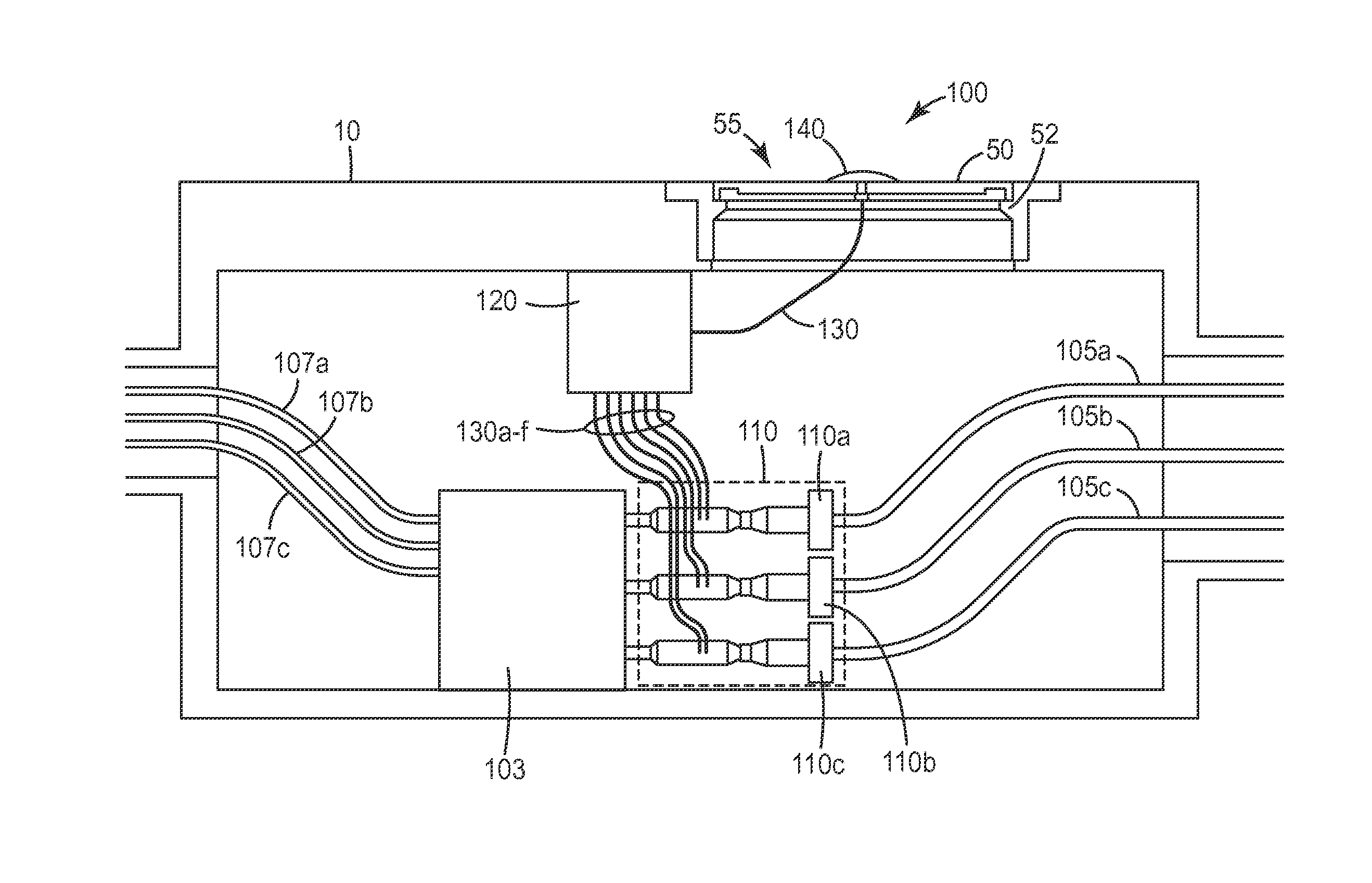
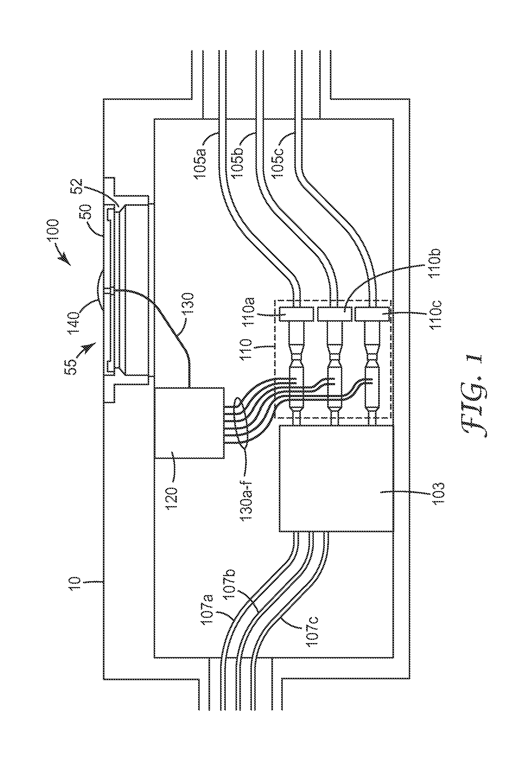
The invention is an underground data communication system that includes a transceiver and a monitoring device. The monitoring device can be a sensor that provides real-time data about the vault's condition. The system also includes a gateway unit that relays the data to an entity outside of the vault. The gateway unit can communicate wirelessly with other monitoring devices and can perform local analysis and interpretation of the data. The system can also communicate with an upstream aggregation node or cloud server. The invention allows for the secure and efficient communication of condition information about the vault, which can be useful in preventing hazardous conditions and ensuring safe operation of the vault.

Problems solved by technology

A sizeable portion of that equipment (˜18% for U.S. electric utilities) is located underground, and providing wireless communications between above ground and underground equipment is a serious challenge.
Current methods used to locate underground cable faults are still slow and labor intensive.

Method used


Image

  • Underground data communication apparatus, system, and method
  • Underground data communication apparatus, system, and method
  • Underground data communication apparatus, system, and method

Examples


Embodiment Construction

[0029]In the following Detailed Description, reference is made to the accompanying drawings, which form a part hereof, and in which is shown by way of illustration specific embodiments in which the invention may be practiced. In this regard, directional terminology, such as “top,”“bottom,”“front,”“back,”“leading,”“forward,”“trailing,” etc., is used with reference to the orientation of the Figure(s) being described. Because components of embodiments of the present invention can be positioned in a number of different orientations, the directional terminology is used for purposes of illustration and is in no way limiting. It is to be understood that other embodiments may be utilized and structural or logical changes may be made without departing from the scope of the present invention. The following detailed description, therefore, is not to be taken in a limiting sense, and the scope of the present invention is defined by the appended claims.

[0030]An underground data communication app...


PUM


Abstract

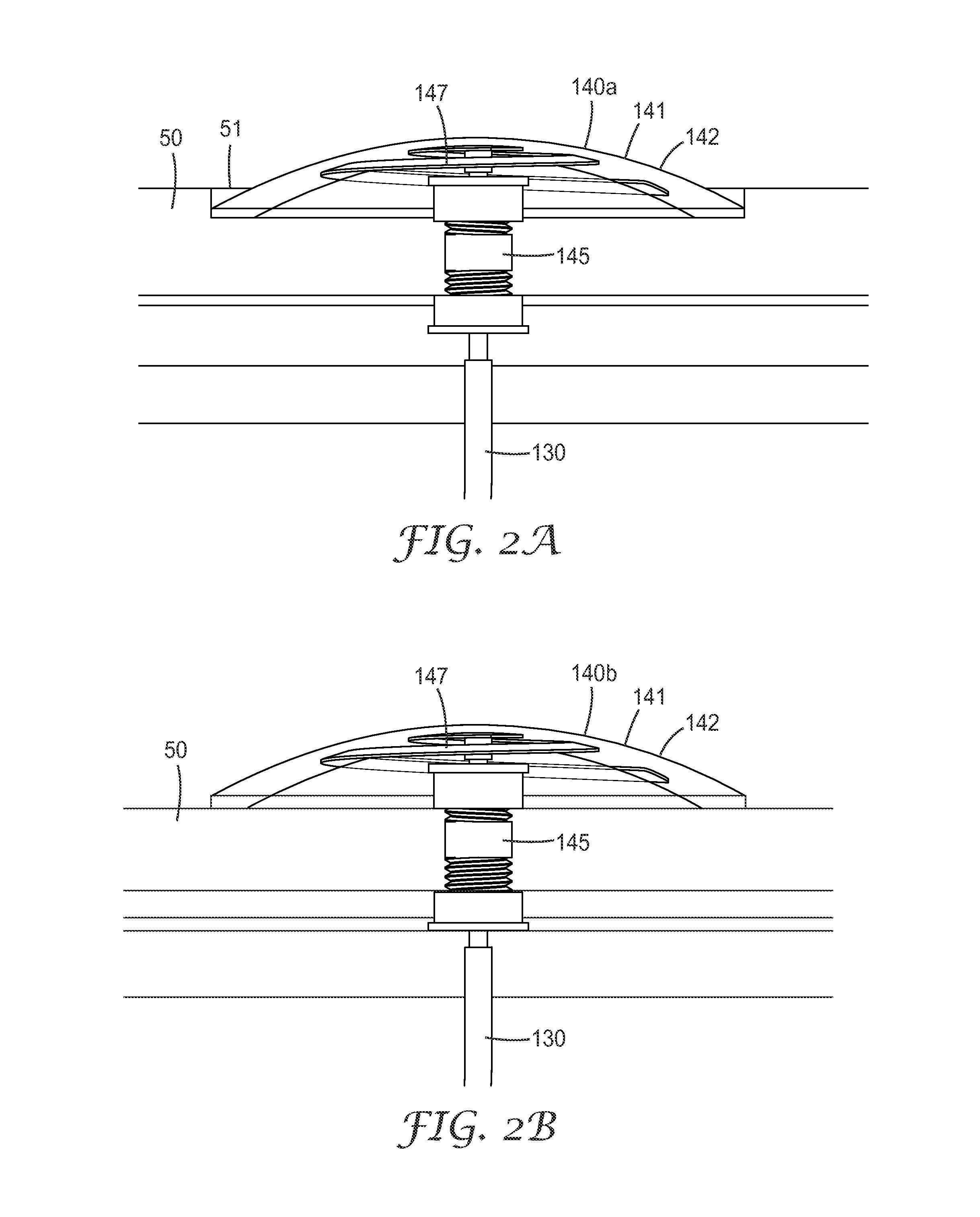
An underground data communication apparatus, system, and method are described. The data communication system includes a transceiver disposed on an entrance port to an underground vault or enclosure, where the transceiver includes a rugged housing, where at least a portion of the rugged housing extends above the surface of the entrance port. A monitoring device is disposed in the vault. The monitoring device can be a sensor that provides data related to a real-time condition within the vault. In addition, the data communication system includes a gateway unit that relays the data to the transceiver. The gateway / transceiver can take a combination of wireless and / or wired signals from the monitoring device which provides real-time data regarding environmental, component, and / or other electronic equipment conditions for those components / equipment disposed within the vault.

Description

BACKGROUND[0001]Machine to machine communication is becoming increasingly important to the energy, communications, and security markets, among others. Supervisory Control and Data Acquisition (SCADA) systems used in those industries rely on inputs from remotely located sensors to function properly. SCADA systems can also output signals to actuate remote equipment in the field. A sizeable portion of that equipment (˜18% for U.S. electric utilities) is located underground, and providing wireless communications between above ground and underground equipment is a serious challenge.[0002]Current methods used to locate underground cable faults are still slow and labor intensive. Even relatively short outages can be used against utilities and lead to rate adjustments for customers, so a faster means of locating and fixing underground faults is needed.[0003]Thus, there is a need for communicating wireless signals into and out of underground equipment vaults and other structures where underg...

Claims


Application Information

Patent Timeline
Patent Type & Authority Applications(United States)
IPC IPC(8): G08B21/18H04L29/06H04L29/08H04B13/02H04B3/46H04B1/38H04L12/931
CPCH02G1/00H02G9/10H04L12/10G08B21/185H04L67/12H04B3/46H04B13/02H04L49/351H04L65/102H04B1/38
Inventor RODRIGUEZ, JR., ERNESTO M.AMANN, VAUGHN G.SCHRIX, LARSWEICHOLD, JENSLAPRAIS, ANNE-MAUD B.
Owner 3M INNOVATIVE PROPERTIES CO
Learn More