Eureka AIR delivers breakthrough ideas for toughest innovation challenges, trusted by R&D personnel around the world.

Wound care bandage and method of wound healing

Active Publication Date: 2016-07-28
GARWOOD LAB LLC
View PDF6 Cites 9 Cited by
  • Summary
  • Abstract
  • Description
  • Claims
  • Application Information

AI Technical Summary

Benefits of technology

The invention is a system that combines a wound care bandage with wound treatment. The bandage has a layer that absorbs bodily fluids and two electrodes that provide electrical current to accelerate healing. The bandage is comfortable for the patient, allows for better freedom and simplifies treatment for trained personnel and healthcare providers.

Problems solved by technology

Of course, healing wounds has long been problematic for a plurality of reasons.
For example, some wounds are difficult to heal because of the physical condition of the patient or the nature of the wound.
In addition, some wounds simple refuse to heal even when the patient is under the care of skilled health care professionals.
However, the current methods for using any of the electronic methods require a variety of different pieces of equipment and often require the patient to remain tethered to equipment with cords leading from the patient to the equipment.
In addition, patients that are not already restricted in bed typically will not follow through with its use of these treatment devices and thus the self-efficacy ratings for these devices are low.
In addition, these devices are not widely used because it also requires a lot of set-up time to put these devices in place.
These devices must be set-up next to the patients and the cords that are associated with these devices have to properly routed by medical providers, all of which takes time and expense.
Electrodes used in the treatments are also very difficult to place properly, and improper placement of the electrodes will oftentimes result in ineffective medical treatment.

Method used


Image

  • Wound care bandage and method of wound healing
  • Wound care bandage and method of wound healing
  • Wound care bandage and method of wound healing

Examples


Embodiment Construction

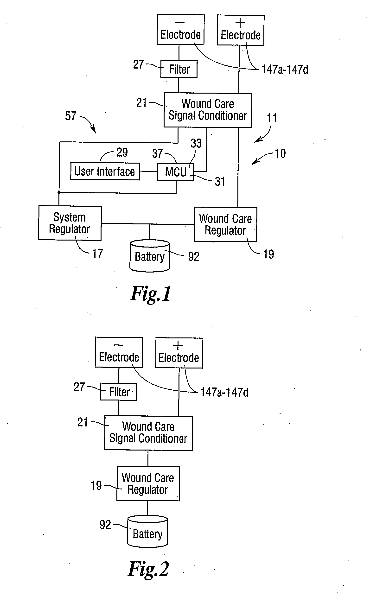
[0038]As shown in FIG. 1, there is a wound healing system 10. The wound healing system includes a battery 92, and wound care bandage electronics 93 that include a system regulator 17, a wound care regulator 19, a wound care signal conditioner 21, snap button electrodes 147a, 147b, 147c and 147d, a filter 27, a user interface 29 and a programmed wound care microcontroller 31 (hereinafter referred to as wound care MCU 31).

[0039]FIGS. 2-4 provide a more detailed breakdown of FIG. 1. FIG. 2 details the main power path wherein the battery 92 powers the wound care regulator 19 and powers the wound care signal conditioner 21. FIG. 3 details the control lines from the user interface 29 to the wound care MCU 31 to the wound care signal conditioner 21. As shown in FIG. 4 the battery 92 powers the system regulator 17 and powers the wound care MCU 31. The filter 27 shown in FIG. 1 is for oscillating current and for preventing undesirable low frequencies to pass, and the filter 27 connects to th...


PUM


Abstract

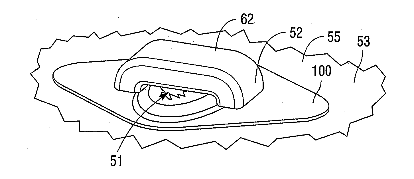
A wound healing system and a wound care bandage are provided. The wound care bandage has an electronics housing that houses a battery and wound care microcontroller. A bandage layer is provided and it defines a pad recess in which a pad is disposed. The pad has channels to allow for airflow. The wound care bandage at least first and second snap button electrodes, but there may be more snap button electrodes in other preferred embodiments. There are also electrically conductive adhesive strips with one being in contact with each of the first and second snap button electrodes. When current is controllably supplied to the first and second snap button electrodes a plurality of electric current flow paths are generated and that extend across the wound and stimulate the healing of the wound. The wound care bandage can be monitored and controlled wirelessly.

Description

CROSS REFERENCE TO RELATED APPLICATION[0001]This application claims priority to U.S. Provisional Application having Ser. No. 62 / 050,795 filed on Sep. 16, 2014 the entire disclosure of which is hereby incorporated herein by reference.TECHNICAL FIELD OF INVENTION[0002]This invention is directed to patients having wounds and accelerating the healing process of the wound with a wound care bandage.BACKGROUND OF INVENTION[0003]When a person suffers an injury or has surgery resulting in a wound it is critical that the wound be closed and heals as quickly as possible. Such rapid wound healing will, among other things, increase patient comfort, decrease the risk of the wound re-opening, decrease the risk of re-injuring the wound site, and decrease the length of a hospital stay and decrease scarring.[0004]Of course, healing wounds has long been problematic for a plurality of reasons. For example, some wounds are difficult to heal because of the physical condition of the patient or the nature ...

Claims


Application Information

Patent Timeline
IPC IPC(8): A61F13/00A61F15/00A61F13/02
CPCA61F13/00063A61F13/0243A61F15/00A61F13/025A61F13/0256A61F13/0206A61N1/0468A61N1/0492
Inventor BACON, WAYNEGELLMAN, GREGG
Owner GARWOOD LAB LLC
Why Eureka
Eureka Blog
Learn More