
Device for reducing head and neck injury for helmet wearer

a technology of head and neck injury and helmet, which is applied in the direction of helmet covers, protective garments, garment special features, etc., can solve the problems of body injury to participants, lack of protection of conventional helmets and collars, and various deficiencies of conventional safety gear, so as to reduce the risk of head or spine injury

Active Publication Date: 2016-07-28
NAGELY SCOTT W
View PDF3 Cites 13 Cited by
  • Summary
  • Abstract
  • Description
  • Claims
  • Application Information

AI Technical Summary

Benefits of technology

The present invention provides a motion restrictor that reduces the risk of head or spine injury by restricting the movement of a helmet. The motion restrictor device includes a harness, helmet-engagement component, and brake assembly. The helmet-engagement component is positioned on the user's harness and has surfaces that shift along with the movement of the helmet while maintaining contact with it. The brake assembly restricts the movement of the helmet-engagement component to prevent injurious movement. This invention solves problems and limitations of prior art safety devices used with helmets.

Problems solved by technology

Similarly, participants also use protective gear when taking part in physical sports activities that do not involve a vehicle (e.g., snow skiing, ice hockey, or football) but can cause bodily injury to the participant.
However, this conventional safety gear has various deficiencies.
For instance, conventional helmets and collars lack sufficient protection when the operator experiences a head-first collision with an external object.
More particularly, conventional safety gear inadequately restricts compression of the operator's neck and spine during a head-first collision.
Additionally, to the extent that any prior art safety gear provides some nominal restriction to compression of the operator's neck and spine, such equipment excessively restricts the helmet's free range of movement during normal operation.

Method used


Image

  • Device for reducing head and neck injury for helmet wearer
  • Device for reducing head and neck injury for helmet wearer
  • Device for reducing head and neck injury for helmet wearer

Examples


Embodiment Construction

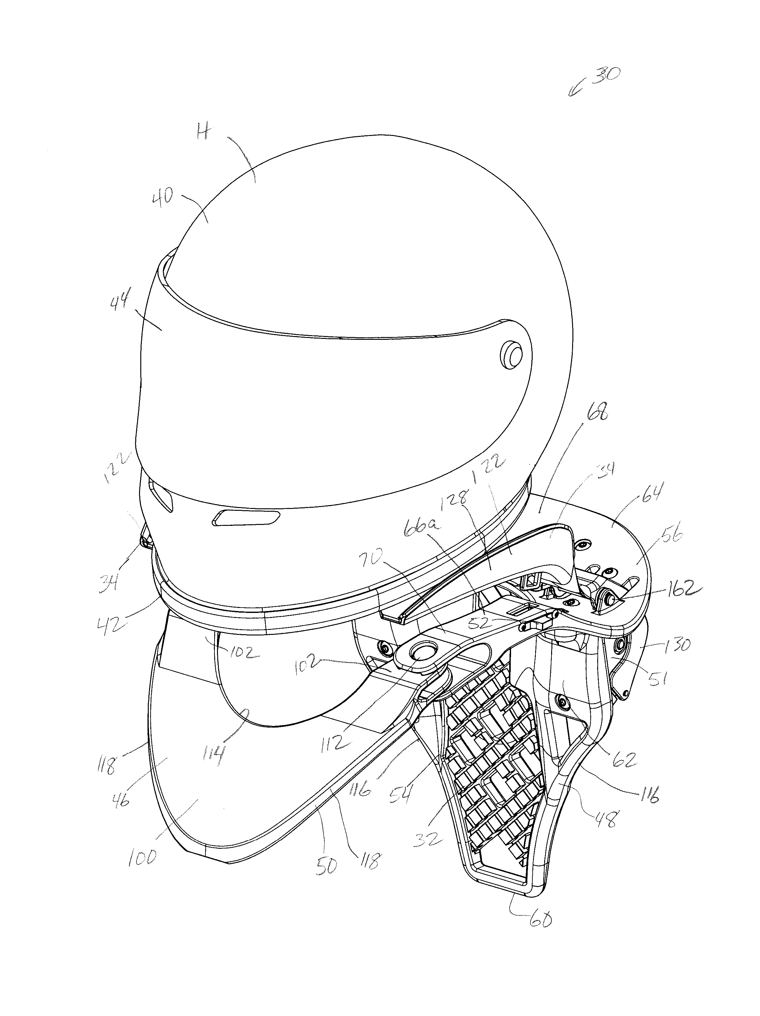
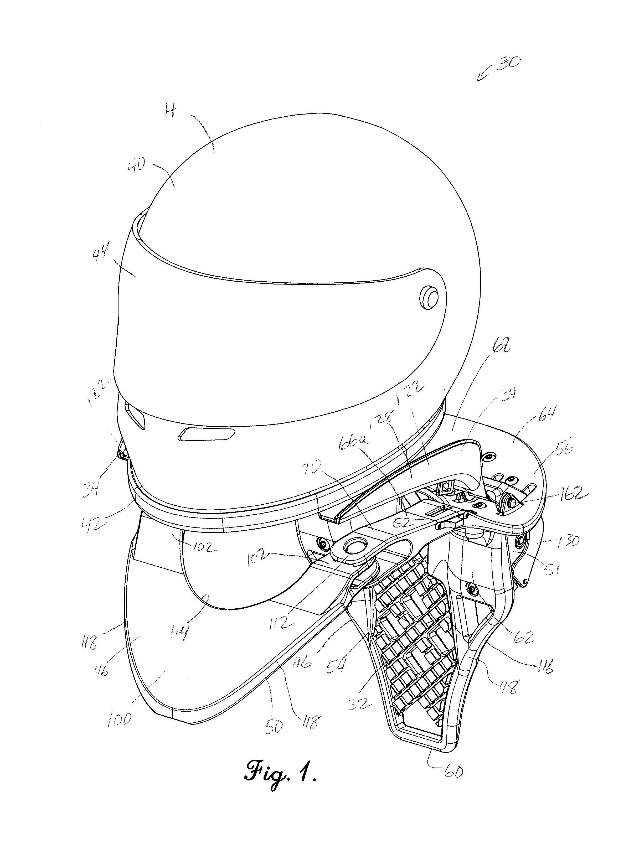
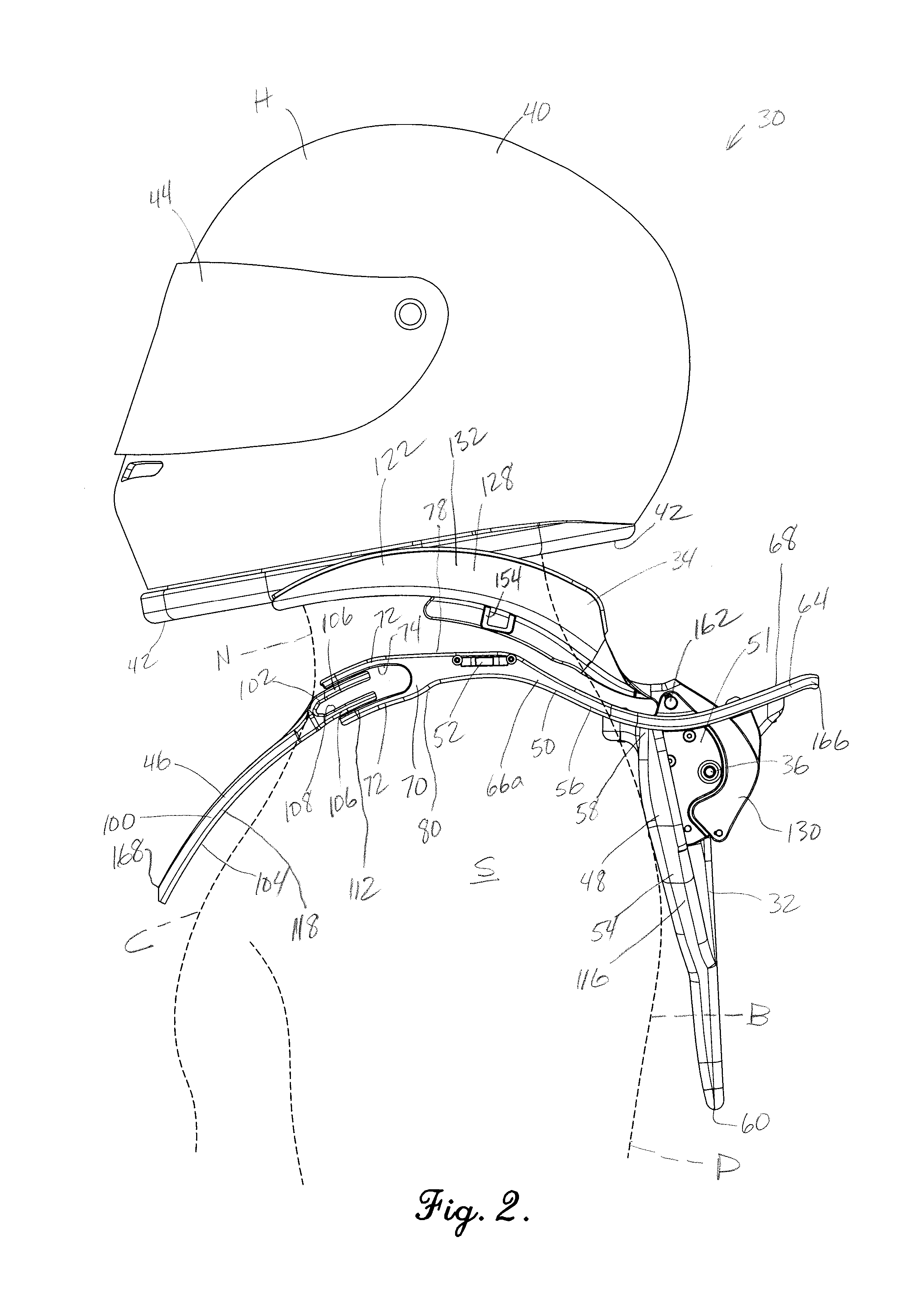
[0037]Turning initially to FIGS. 1 and 2, a motion restrictor 30 is constructed in accordance with a preferred embodiment of the present invention. The motion restrictor 30 is configured to be worn by a user P to control the movement of a helmet H when the helmet H is exposed to excessive acceleration and / or external force. More particularly, the motion restrictor 30 is configured to decelerate and stop the helmet H in response to excessive acceleration and / or external force, particularly when the acceleration or force could lead to injury of the user. For instance, the motion restrictor 30 is configured to be worn by the user P when the user P wears the helmet H while riding a vehicle (e.g., an off-road vehicle such as a bicycle, motorcycle, all terrain vehicle (ATV), automobile, etc.). It will be appreciated by those of ordinary skill in the art that the user P can be exposed to excessive acceleration and / or external forces when the vehicle (not shown) travels over terrain that is...


PUM


Abstract

A motion restrictor device is operable to be worn with a protective helmet to reduce the risk of head or spine injury caused by injurious movement of the helmet. The device includes a helmet-engaging component supported on a harness. The component presents helmet-engagement surfaces positioned on opposite sides of the neck of the user. The component is operable to yieldably bias each of the helmet-engagement surfaces toward the helmet when the device is worn, such that contact with the helmet is maintained as the helmet-engagement surface shifts through a range of motion. The device also includes a brake assembly that restricts shifting of at least one of the helmet-engagement surfaces in response to injurious movement of the helmet.

Description

RELATED APPLICATION[0001]This application claims the benefit of U.S. Provisional Application Ser. No. 62 / 107,867, filed Jan. 26, 2015, entitled DEVICE FOR REDUCING HEAD AND NECK INJURY FOR HELMET WEARER, which is hereby incorporated in its entirety by reference herein.BACKGROUND[0002]1. Field[0003]The present invention relates generally to a device operable to restrict motion of a protective helmet. More specifically, embodiments of the present invention concern a motion restrictor device that is designed to reduce the risk of injury caused by excessive or overly rapid movement of a helmet.[0004]2. Discussion of Prior Art[0005]Personal protective safety gear has long been used in connection with various types of physical activity to provide cushioning and to protect the user from injurious movement as a result of the activity. For instance, participants in various vehicular sporting activities have long used safety helmets to protect the user's head from injurious contact with an ex...

Claims


Application Information

Patent Timeline
Patent Type & Authority Applications(United States)
IPC IPC(8): A42B3/04A41D13/05
CPCA42B3/0473A41D2400/70A41D2400/44A41D13/0512A41D13/0531
Inventor NAGELY, SCOTT W.KOVACEVICH, IAN D.
Owner NAGELY SCOTT W
Learn More