System and method for adjusting engine airflow

a technology of engine airflow and system, applied in the direction of electric control, speed sensing governor, instruments, etc., can solve the problems of engine performance being less potent in humid conditions, engine output of both map sensor and maf sensor may be affected by humidity, etc., to improve engine air-fuel ratio control, engine performance, and engine airflow estimate more accurate

Active Publication Date: 2016-06-23
FORD GLOBAL TECH LLC
View PDF0 Cites 7 Cited by
  • Summary
  • Abstract
  • Description
  • Claims
  • Application Information

AI Technical Summary

Benefits of technology

The patent is about a method to estimate the amount of air that enters an engine using a manifold absolute pressure (MAP) sensor and a mass airflow (MAF) sensor. These sensors can be affected by humidity, which can affect engine performance. By adjusting engine spark timing and airflow based on the humidity, the engine can produce the same amount of torque regardless of the humidity level. This method can be applied to turbocharged and naturally aspirated engines, as well as different types of fuel systems. The technical effect is to provide consistent engine performance regardless of humidity levels.

Problems solved by technology

However, output of both the MAP sensor and MAF sensor may be affected by humidity in air since output of each sensor is not compensated for humidity.
As a result, engine performance during humid conditions may not be as potent as engine performance during low humidity conditions.

Method used


Image

  • System and method for adjusting engine airflow
  • System and method for adjusting engine airflow
  • System and method for adjusting engine airflow

Examples


Embodiment Construction

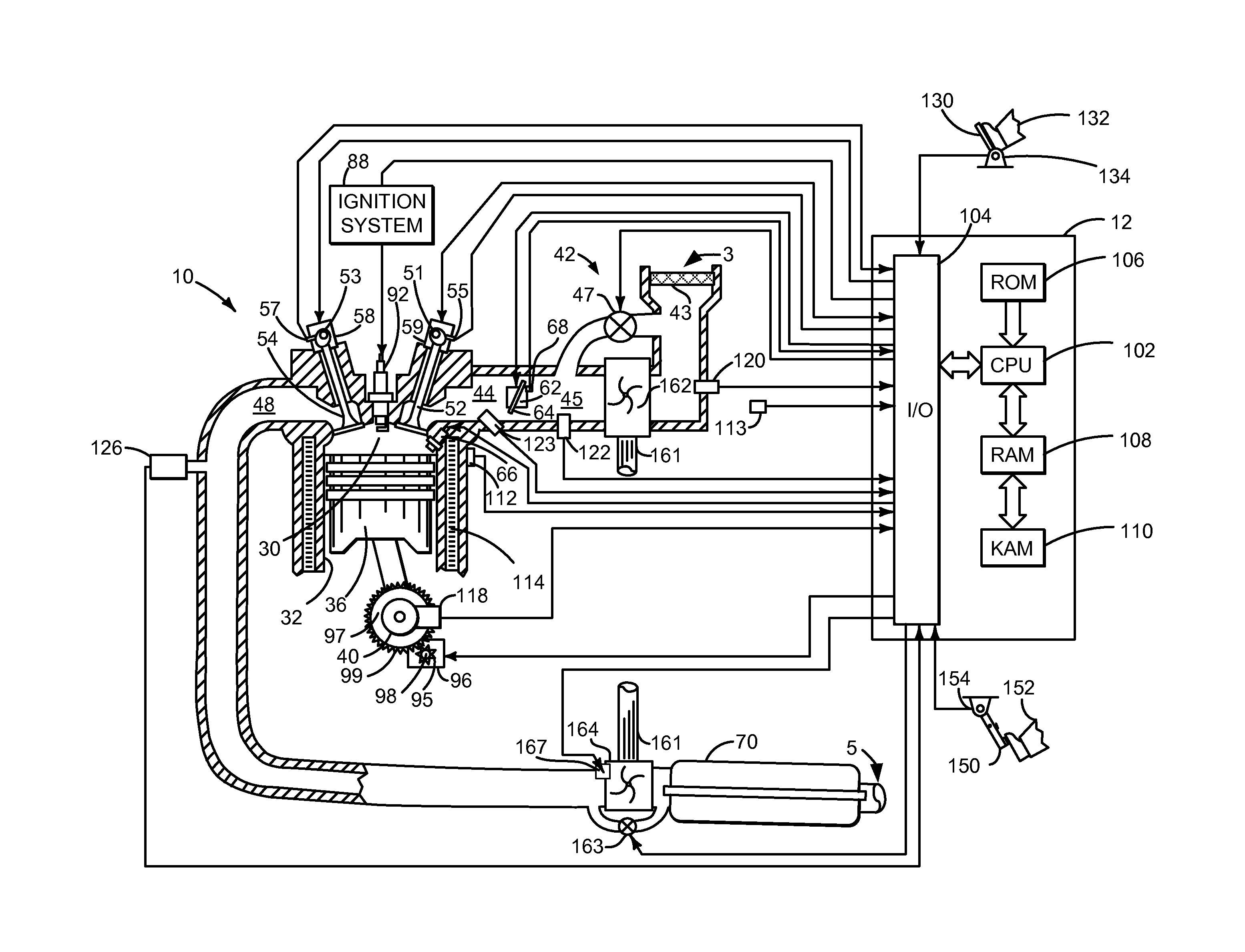
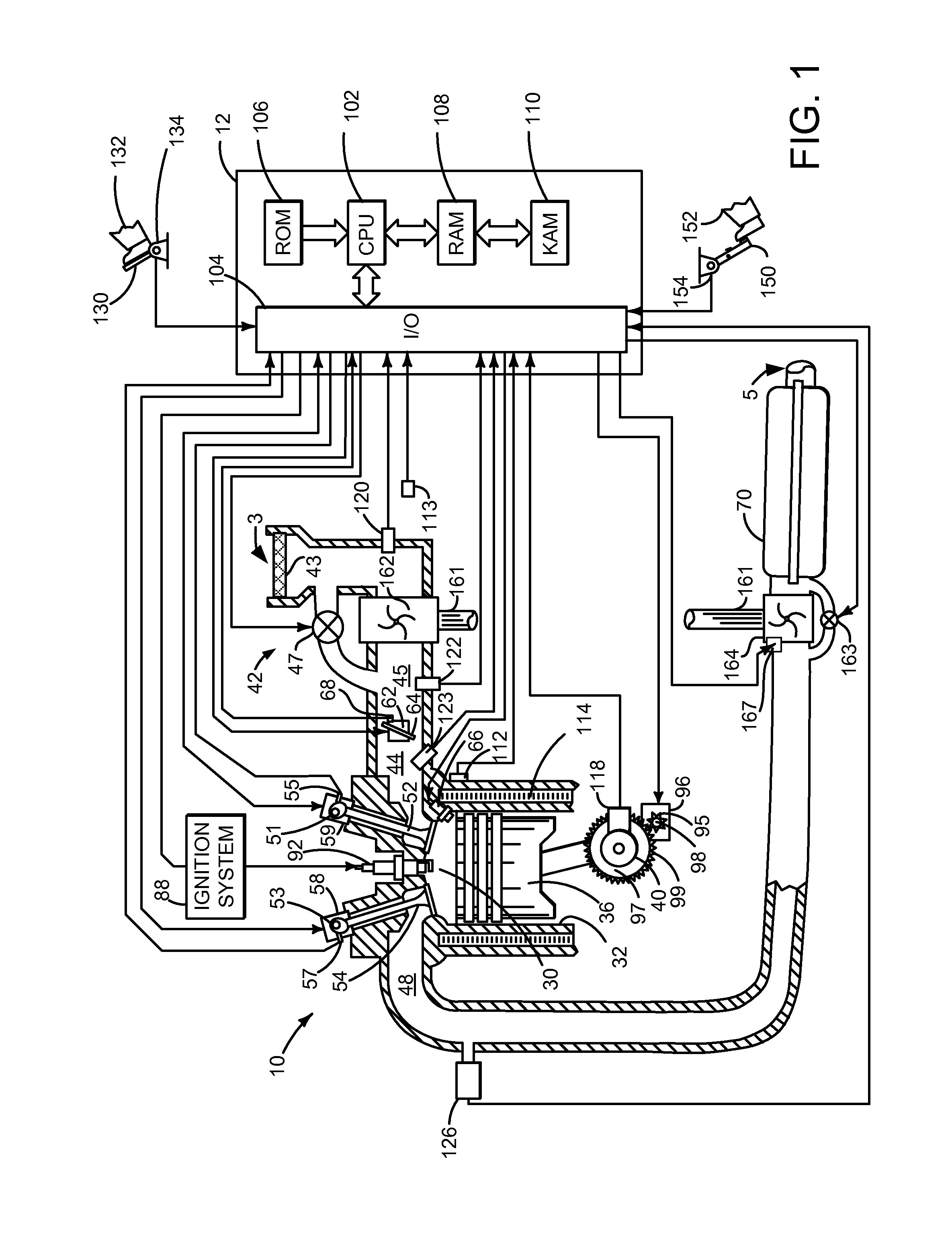
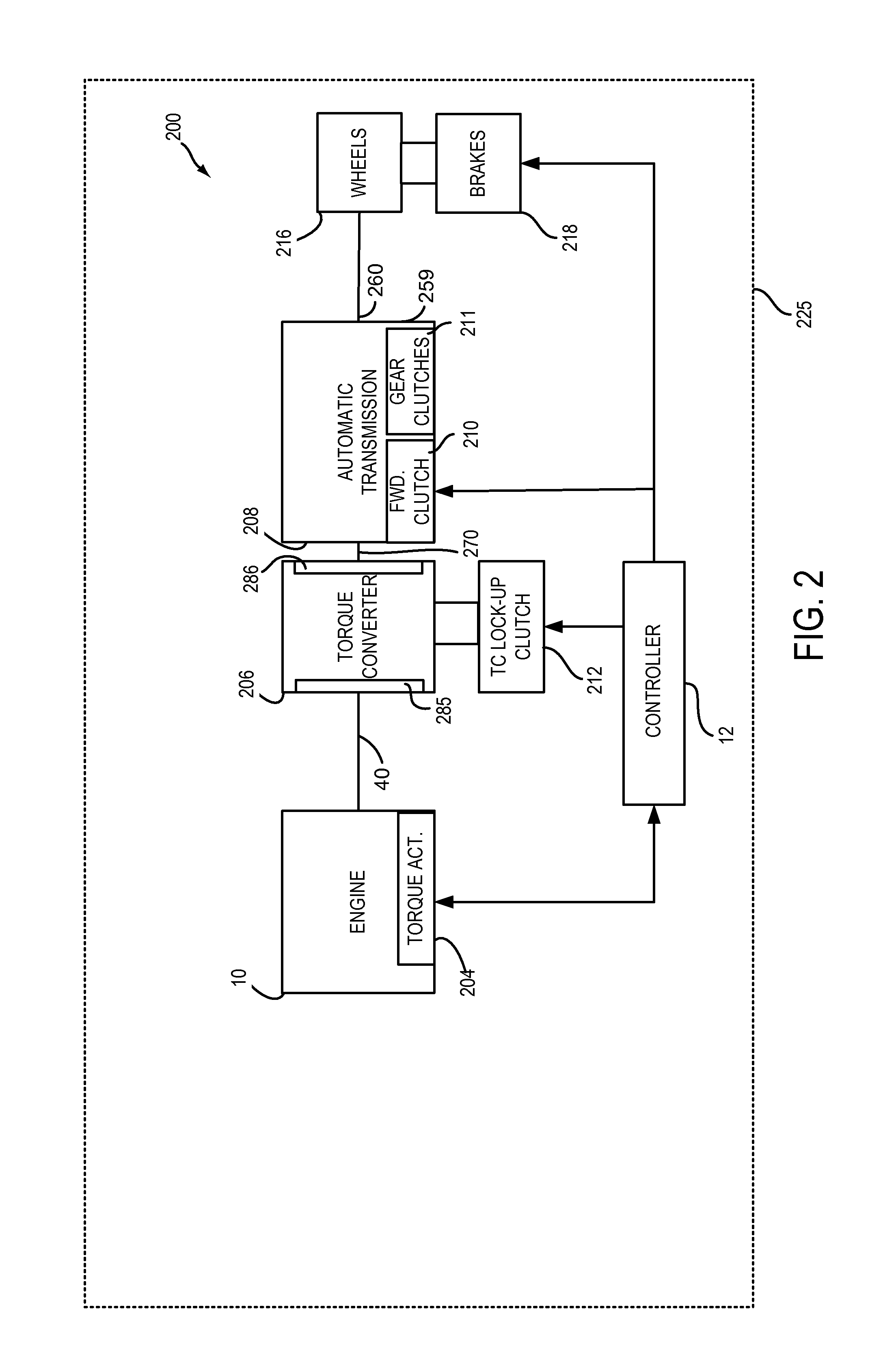
[0013]The present description is related to operating an engine at varying ambient humidity levels. The engine may be configured as is shown in FIG. 1 in a driveline as is shown in FIG. 2. The engine of FIG. 1 may operate as is described in FIGS. 3-5. The system of FIG. 1 may include torque control as described by the block diagram of FIG. 6. The system of FIG. 1 may also include executable instructions to provide the engine operating method described in FIG. 7. The engine operating method of FIG. 7 modifies engine operation to improve engine torque output during low and high ambient humidity conditions. The engine may operate as is shown in the operating sequence of FIG. 8.

[0014]Referring to FIG. 1, internal combustion engine 10, comprising a plurality of cylinders, one cylinder of which is shown in FIG. 1, is controlled by electronic engine controller 12. Engine 10 includes combustion chamber 30 and cylinder walls 32 with piston 36 positioned therein and connected to crankshaft 40...


PUM


Abstract

Methods and systems for operating an engine during conditions where ambient humidity changes over time are presented. In one non-limiting example, an engine airflow is adjusted to increase engine airflow during high humidity conditions such that an engine may provide equivalent torque output during the high humidity conditions as compared to when the engine is operated during low humidity conditions.

Description

BACKGROUND / SUMMARY[0001]An amount of air entering an engine may be estimated via a manifold absolute pressure (MAP) sensor or a mass airflow (MAF) sensor. The MAP sensor has advantages of directly sampling intake manifold pressure to determine cylinder air charge. Consequently, the MAP sensor may provide more accurate engine airflow estimate when the engine intake manifold pressure is changing due to engine load transients. On the other hand, the MAF sensor provides an accurate measure of air mass entering the engine during steady state conditions which may improve engine air-fuel ratio control during steady state conditions. However, output of both the MAP sensor and MAF sensor may be affected by humidity in air since output of each sensor is not compensated for humidity. As a result, engine performance during humid conditions may not be as potent as engine performance during low humidity conditions.[0002]The inventors herein have recognized the above-mentioned issues and have deve...

Claims


Application Information

Patent Timeline
IPC IPC(8): F02D41/00F02D41/02F02D41/18F02D9/02F02D35/00
CPCF02D41/0002F02D9/02F02D2009/0225F02D41/18F02D41/021F02D35/00F02D31/002F02D37/02F02D2200/1002F02D41/0065F02B37/18F02P5/1516F02P5/152F02D41/0007F02D2200/0406F02D2200/0414F02D2200/0418Y02T10/40
Inventor SURNILLA, GOPICHANDRAHAKEEM, MOHANNADCLARK, TIMOTHY JOSEPHSMITH, STEPHEN B.
Owner FORD GLOBAL TECH LLC
Why Eureka
Try Eureka