Tsunami monitoring system including transmitting antenna for radiating transmission signal for detecting tsunami as radio wave toward sea
- Summary
- Abstract
- Description
- Claims
- Application Information
AI Technical Summary
Benefits of technology
Problems solved by technology
Method used
Image
Examples
first embodiment
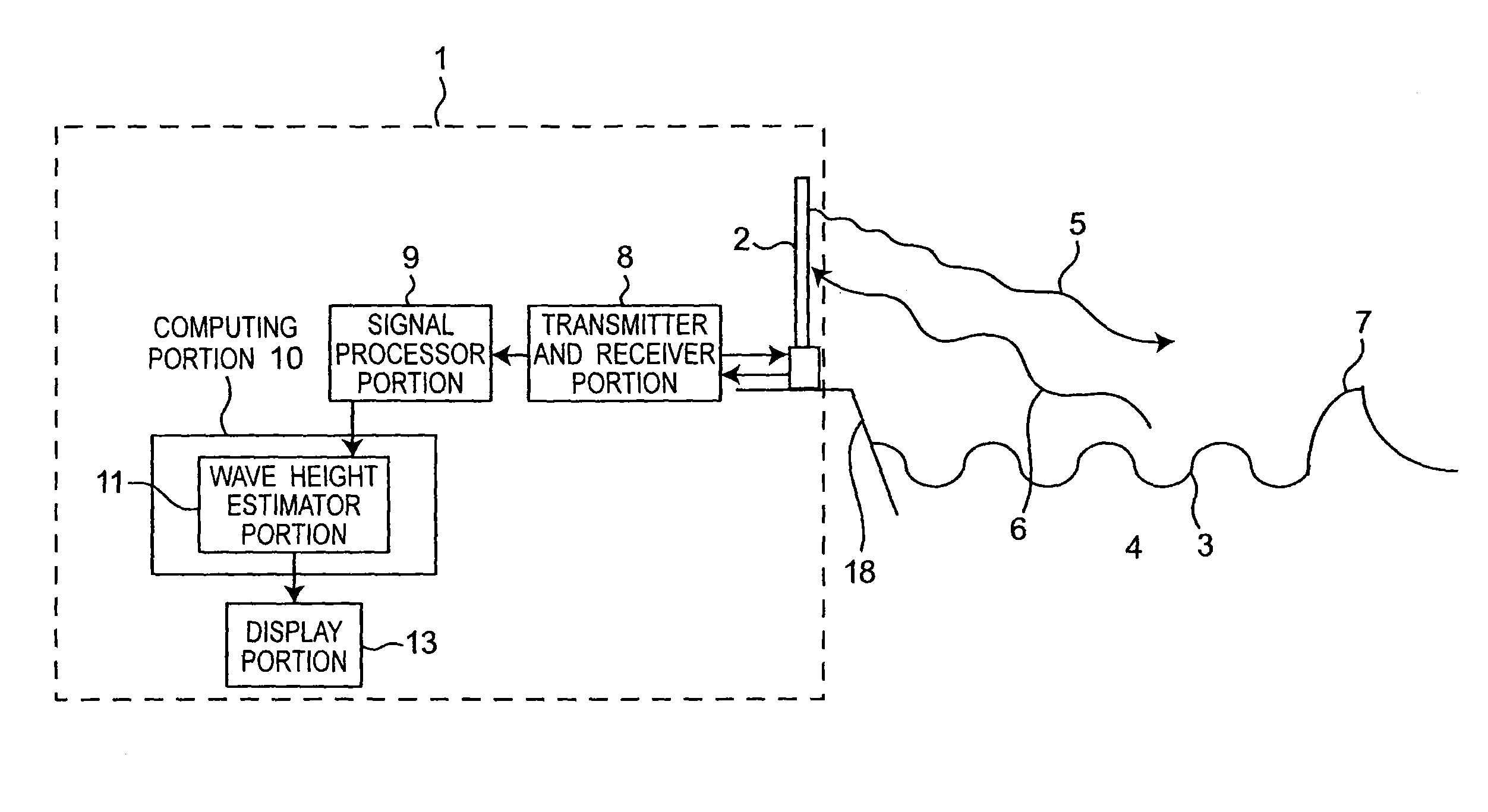
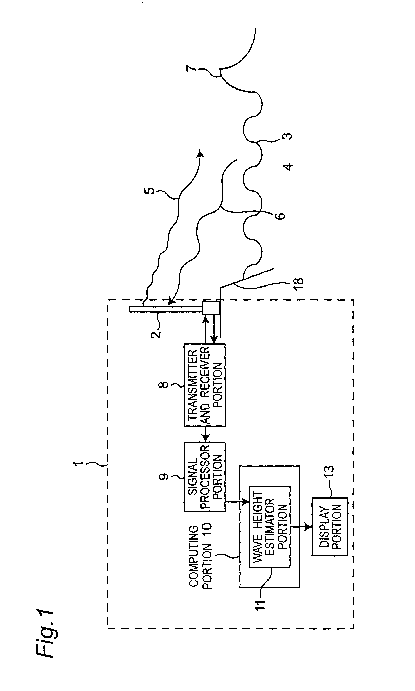
[0043]FIG. 1 is a block diagram showing a tsunami monitoring system 1 and its peripheral components, according to a first embodiment of the present invention. The tsunami monitoring system 1 of FIG. 1 is configured to include a transmitting and receiving antenna 2 provided in a position such that a transmission radio wave 5 can scan a sea surface, a transmitter and receiver portion 8, a signal processor portion 9, a computing portion 10, and a display portion 13. In addition, the computing portion 10 is configured to include a wave height estimator portion 11 configured to include a computer and a program. In addition, the transmitting and receiving antenna 2 is placed on a land 18. However, the invention is not limited thereto, the transmitting and receiving antenna 2 may be placed at any position such that the transmission radio wave 5 can scan the sea surface, for example, the transmitting and receiving antenna 2 may be placed on a sea 4. In addition, the transmitting and receivi...
second embodiment
[0063]FIG. 4 is a block diagram showing a tsunami monitoring system 1A and its peripheral components, according to a second embodiment of the present invention. As compared with the tsunami monitoring system 1 of FIG. 1, the tsunami monitoring system 1A of FIG. 4 is characterized in that a computing portion 10A is provided in place of the computing portion 10.
In addition, as compared with the computing portion 10 of FIG. 1, the computing portion 10A is characterized in that a wave height estimator portion 11A is provided in place of the wave height estimator portion 11 and a water depth distribution data memory 17 of a first memory for storing the water depth distribution data of the static water depth h of the sea 4 around the transmitting and receiving antenna 2 is further provided. In this case, although a range around the transmitting and receiving antenna 2 is arbitrarily determined depending on the range in which the transmission radio wave 5 can scan the sea surface or the li...
third embodiment
[0072]The case where only the transmitting and receiving antenna 2 for measuring flow velocity Ur in the direction of the radius r is installed has been described in the second embodiment, it becomes possible to more accurately estimate the wave height η of the tsunami 7 by further installing a transmitting and receiving antenna 2 for measuring the flow velocity Vθ in the direction of the rotational angle θ.
[0073]When the equations (2) and (3) of motion of the first embodiment are deformed and the dimension of the wave height η is assumed to be sufficiently small by comparison to the dimension of the total water depth D, then the following equation (8) and equation (9) are derived when D=h is substituted into the above deformed equation of motion and orderly arranged since the dimension of the total water depth D is approximately equal to the dimension of the static water depth h:
∂Mr∂t+gh∂η∂r=0(8)∂Mθ∂t+gh1r∂η∂θ=0(9)
[0074]Next, when the equation (8) differentiated by the radius r and...
PUM
 Abstract
Description
Claims
Application Information
 - R&D
- Intellectual Property
- Life Sciences
- Materials
- Tech Scout
- Unparalleled Data Quality
- Higher Quality Content
- 60% Fewer Hallucinations
Browse by: Latest US Patents, China's latest patents, Technical Efficacy Thesaurus, Application Domain, Technology Topic, Popular Technical Reports.
© 2025 PatSnap. All rights reserved.Legal|Privacy policy|Modern Slavery Act Transparency Statement|Sitemap|About US| Contact US: help@patsnap.com


