
Apparatus and method for controlling video wall

a technology of video wall and apparatus, applied in the field of apparatus and method for controlling video wall, can solve the problem that the video wall device tends to have color deviation between the display device and the display devi

Active Publication Date: 2016-06-02
SAMSUNG ELECTRONICS CO LTD
View PDF3 Cites 27 Cited by
  • Summary
  • Abstract
  • Description
  • Claims
  • Application Information

AI Technical Summary

Benefits of technology

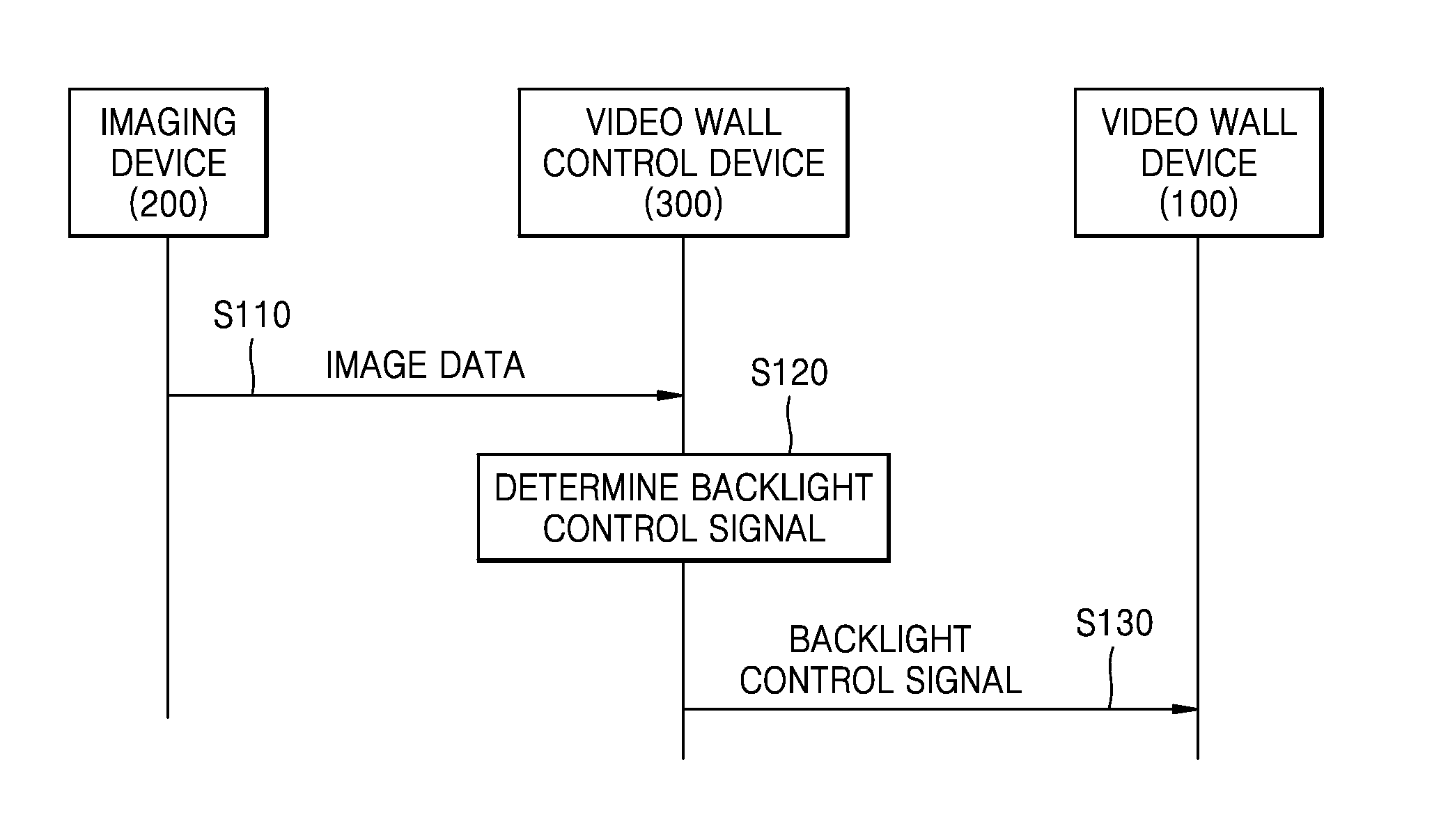
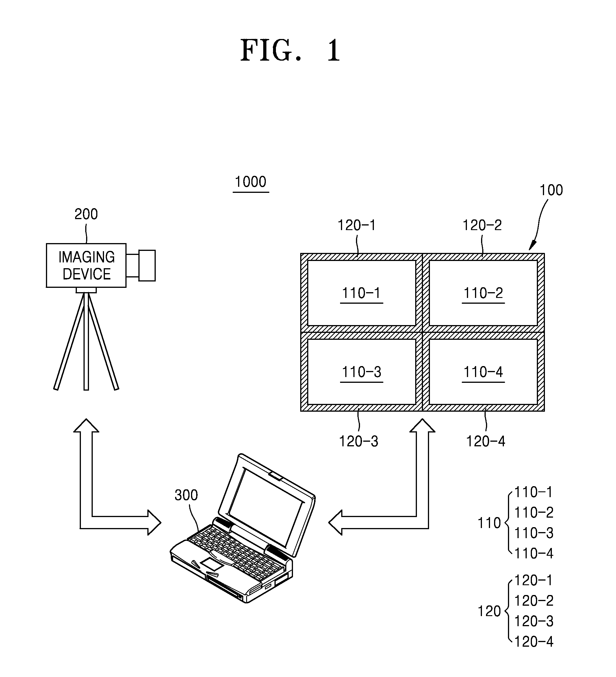
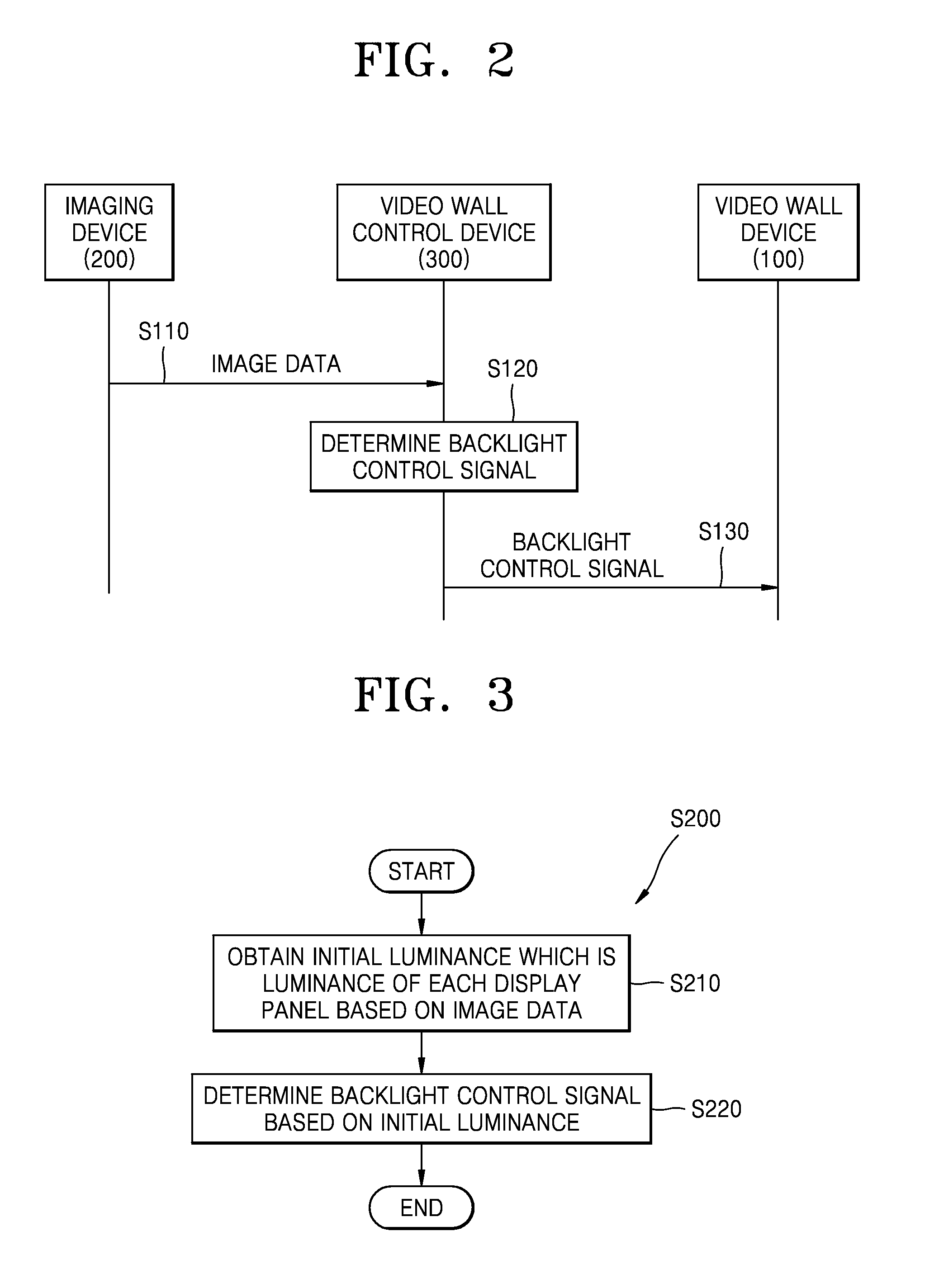
The patent describes a video wall control device and method that can adjust the brightness of each display panel in a video wall device using a backlight control system. The device can determine the initial brightness of each panel and adjust the backlight control to achieve a reference brightness. The method can also capture a second image to determine if the backlight control needs to be adjusted and transmit the adjusted control to the video wall device. The technical effect of this patent is to provide a more precise and effective control over the brightness of each display panel in a video wall device, allowing for better adjustment of the overall display brightness.

Problems solved by technology

However, video wall devices tend to have color deviation between the display devices that is visible to the naked eye.

Method used


Image

  • Apparatus and method for controlling video wall
  • Apparatus and method for controlling video wall
  • Apparatus and method for controlling video wall

Examples


Embodiment Construction

[0041]The disclosed examples may have different forms and should not be construed as being limited to the descriptions set forth herein. The examples are described below in sufficient detail to enable those of ordinary skill in the art to embody and practice the examples, and the disclosure is defined only by the scope of claims.

[0042]The terminologies used herein will be described briefly, and the examples will be described in more detail.

[0043]The terminology used herein may be general terminology which is currently widely used in consideration of functions of the examples, but may also be changed according to intentions of technicians of ordinary skill in the art, precedent, appearance of new technology, etc. Further, in specific cases, terminology arbitrarily selected by the applicant may be used, and in such cases, the meaning will be described in detail in a corresponding portion of the description. Accordingly, the terminology used herein should be defined based not simply on...


PUM


Abstract

A video wall control device is provided in which a data processor is configured to determine a backlight control signal controlling an intensity of light supplied by at least one backlight unit among a plurality of backlight units based on image data obtained by capturing an image of a video wall device including a plurality of display panels and the plurality of backlight units supplying the light to each of the plurality of display panels, and signal transmission and reception circuitry configured to transmit the backlight control signal to the video wall device.

Description

CROSS-REFERENCE TO RELATED APPLICATION[0001]This application is based on and claims priority under 35 U.S.C. §119 to Korean Patent Application No. 10-2014-0169179, filed on Nov. 28, 2014, in the Korean Intellectual Property Office, the disclosure of which is incorporated by reference herein in its entirety.BACKGROUND[0002]1. Field[0003]The disclosure relates to an apparatus and method for controlling a video wall, for example, to an apparatus and method for controlling a video wall capable of adjusting luminances among a plurality of display panels through control of a backlight unit.[0004]2. Description of Related Art[0005]A video wall device is a device configured to use a plurality of display devices as one integrated display device. That is, a video wall device includes a plurality of display devices, and the plurality of display devices form one large screen. A video wall device is also referred to as a large format display (LFD) device.[0006]However, video wall devices tend to...

Claims


Application Information

Patent Timeline
Patent Type & Authority Applications(United States)
IPC IPC(8): G09G3/34G06F3/14G06F3/00
CPCG09G3/3406G06F3/005G09G2320/0233G09G2320/0626G06F3/1446G09G2320/062G09G2320/0693G06F3/04897G09G3/20G09G3/2003G09G3/2007
Inventor BEON, NAM-KYUNKIM, MIN-JUNGKWON, OH-YUN
Owner SAMSUNG ELECTRONICS CO LTD
Learn More