
Method and apparatus for cancelling self-interference signal between transmission antenna and reception antenna

a transmission antenna and self-interference technology, applied in the field of wireless communication, can solve the problems of ue to ue inter-link interference, bs to bs inter-link interference, and intra-device self-interference,

Active Publication Date: 2016-05-12
LG ELECTRONICS INC
View PDF0 Cites 6 Cited by
  • Summary
  • Abstract
  • Description
  • Claims
  • Application Information

AI Technical Summary

Benefits of technology

The present invention provides an apparatus and method for cancelling a self-interference signal between a transmission and a reception antenna. The apparatus includes two self-interference signal cancellation units that cancel the self-interference signal based on different channel characteristics. A controller combines the coefficients from the cancellation units to cancel the linear and nonlinear self-interference signals. The method cancels the self-interference signal by comparing the transmitted and received signals and applying the appropriate coefficient based on the channel characteristic. The technical effect of this invention is improved signal quality and reduced interference between the transmitted and received signals.

Problems solved by technology

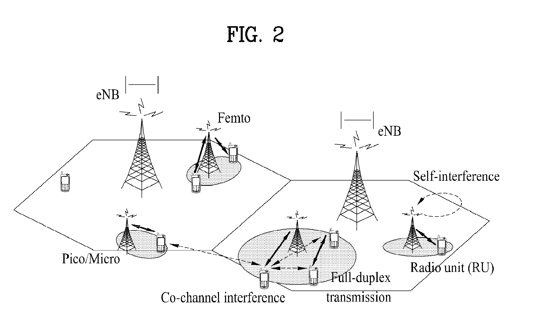
First interference is intra-device self-interference.
In a network that supports FDR, the UE to UE inter-link interference is increasingly caused.
Similarly, in a network state that supports FDR, BS to BS inter-link interference is increasingly caused.
In order to manage FDR, a most serious problem is cancellation of self-interference.
However, methods for effectively cancelling self-interference in an FDR state have not been discussed in detail.

Method used


Image

  • Method and apparatus for cancelling self-interference signal between transmission antenna and reception antenna
  • Method and apparatus for cancelling self-interference signal between transmission antenna and reception antenna
  • Method and apparatus for cancelling self-interference signal between transmission antenna and reception antenna

Examples


Embodiment Construction

[0033]Reference will now be made in detail to the exemplary embodiments of the present invention with reference to the accompanying drawings. The detailed description, which will be given below with reference to the accompanying drawings, is intended to explain exemplary embodiments of the present invention, rather than to show the only embodiments that may be implemented according to the invention. The following detailed description includes specific details in order to provide a thorough understanding of the present invention. However, it will be apparent to those skilled in the art that the present invention may be practiced without such specific details. For example, the following description focuses upon a case in which a mobile communication system is a 3rd generation partnership project (3GPP) long term evolution (LTE) system or a LTE-advanced (LTE-A) system. However, the present technical features, aside from unique features of 3GPP LTE and LTE-A may be applied to any other ...


PUM


Abstract

An apparatus for cancelling a self-interference signal between a transmission antenna and a reception antenna is disclosed. The apparatus includes a first self-interference signal cancellation unit for cancelling a self-interference signal in consideration of a linear channel between the transmission antenna and the reception antenna, a second self-interference signal cancellation unit for cancelling a self-interference signal in consideration of nonlinear channel characteristic between the transmission antenna and the reception antenna or linear characteristic of a radio channel, and a controller for comparing a transmitted signal output from the transmission antenna and a received signal received by the reception antenna to provide a first coefficient to be applied to self-interference signal cancellation of a linear device in the first self-interference signal cancellation unit and a second coefficient to be applied to self-interference signal cancellation of a nonlinear device in the second self-interference signal cancellation unit.

Description

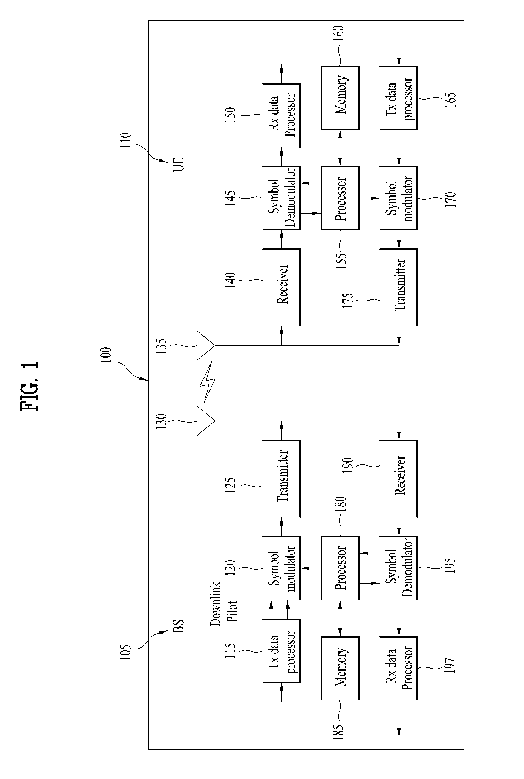
[0001]Pursuant to 35 U.S.C. §119(e), this application claims the benefit of U.S. Provisional Application No. 61 / 984,842, filed on Apr. 27, 2014, which is hereby incorporated by reference as if fully set forth herein.BACKGROUND OF THE INVENTION[0002]1. Field of the Invention[0003]The present invention relates to wireless communication, and more particularly, to a method and apparatus for cancelling a self-interference signal between a transmission (Tx) antenna and a reception (Rx) antenna.[0004]2. Discussion of the Related Art[0005]A full duplex radio (FDR) or full duplex communication scheme refers to a communication scheme for simultaneously supporting transmission and reception using the same resource in one user equipment (UE). In this case, the same resource refers to the same time and the same frequency. FDR communication or full duplex communication is referred to as two-way communication.[0006]FIG. 1 is a diagram illustrating concept of a UE and a base station (BS), which sup...

Claims


Application Information

Patent Timeline
Patent Type & Authority Applications(United States)
IPC IPC(8): H04B15/02H04B1/48
CPCH04B15/02H04B2001/485H04B1/48H04B1/525H04B7/24H04B15/00H04B7/0626H04B7/026
Inventor KIM, JINMINCHUNG, JAEHOONHAHN, GENEBECKLEE, EUNJONGCHOI, KUKHEONNOH, KWANGSEOK
Owner LG ELECTRONICS INC
Learn More