
Diagnostic device for vehicle

Active Publication Date: 2016-05-12
CHU HENRY C
View PDF5 Cites 4 Cited by
  • Summary
  • Abstract
  • Description
  • Claims
  • Application Information

AI Technical Summary

Benefits of technology

The purpose of this patent is to create a device that makes it easy and quick to diagnose and analyze different parts of a car's engine or air conditioning system. It also helps to easily identify and repair any potential issues in a train's air compressing system.

Problems solved by technology

This is expensive because the workers have to purchase the entirety of a number of different meters.
However, the typical diagnostic or analysis devices for diagnosing or analyzing the vehicular engine, air conditioning system, etc. of the vehicles may not be easily used to diagnose or analyze different parameters of the vehicular engine, air conditioning system, etc. of the vehicles, or to identify one or more malfunctions in a locomotive air compressing system.

Method used


Image

  • Diagnostic device for vehicle
  • Diagnostic device for vehicle
  • Diagnostic device for vehicle

Examples


Embodiment Construction

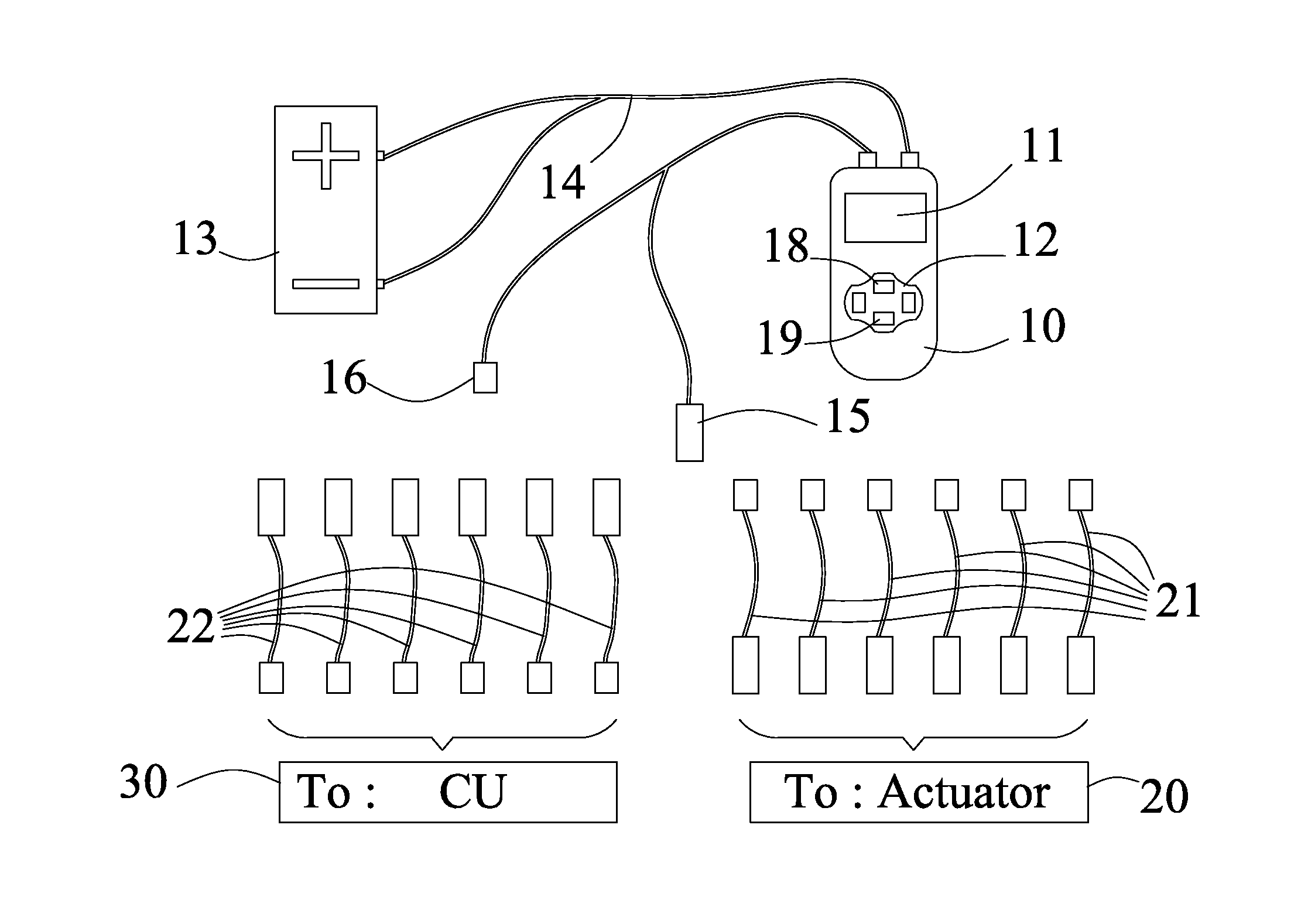
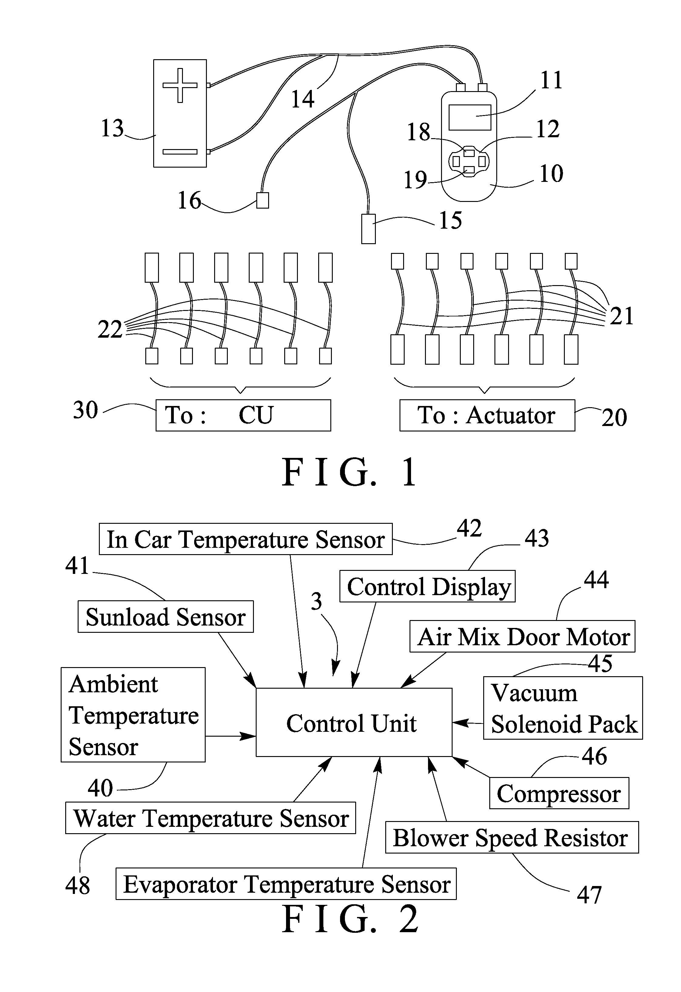
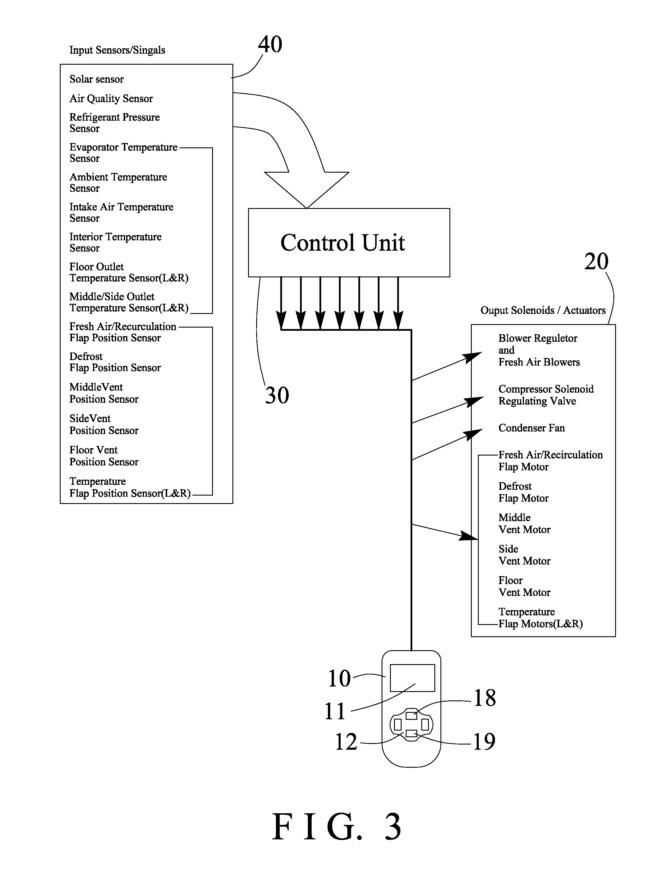
[0021]Referring to the drawings, and initially to FIG. 1, a diagnostic or analysis device in accordance with the present invention comprises a receptacle or housing 10 including a screen or display 11 formed or provided therein, and including a control panel 12 formed or provided thereon, a power source 13, such as a battery 13 is provided for connecting or coupling to the housing 10 with a connecting cable 14 for energizing the display 11 or the like, and the housing 10 further includes one or more (such as two) connectors or adapters or attachments 15, 16 electrically connected or coupled to the housing 10, in which the one or first attachment 15 is provided for connecting or coupling to the actuators 20 with one or more adapters or connectors 21, in series, and the other or second attachment 16 is provided for connecting or coupling to a control unit 30, such as an electrical or diagnostic control unit 30 with one or more adapters or connectors 22, in series.

[0022]As shown in FIG...


PUM


Abstract

A diagnostic device for vehicle includes a housing having a display and a control panel, a control unit connected to the housing, a number of input sensors connected to the control unit for sending input signals to the control unit, and for displaying the input signals on the display, and a number of actuators connected to the control unit for being controlled and actuated by the control unit. The control unit includes an input interface circuit for connecting to the input sensors. The control unit includes an output operation circuit for connecting to the actuators.

Description

BACKGROUND OF THE INVENTION[0001]1. Field of the Invention[0002]The present invention relates to a diagnostic or analysis device for vehicles, and more particularly to a diagnostic or analysis device including an improved and simplified structure or configuration for allowing the user or worker to easily and quickly and readily and effectively diagnose or analyze different parameters of the vehicular engine or air conditioning system of the vehicles, or to identify one or more malfunctions in a locomotive air compressing system and for repairing the locomotive air compressing system.[0003]2. Description of the Prior Art[0004]In conducting an analysis of a vehicular engine, it is common to analyze a number of different parameters with a collection of different meters to perform the various analyses, such as the volt / ohm meter, the primary tacho / dwell meter, the secondary tachometer, the DC current meter, the thermometer, and the pressure meter, etc. This is expensive because the work...

Claims


Application Information

Patent Timeline
IPC IPC(8): G07C5/08
CPCG07C5/0825G07C5/0808G07C2205/02
Inventor CHU, HENRY C.
Owner CHU HENRY C
Learn More