Method and System for Autonomous Vehicles

a technology for autonomous vehicles and vehicles, applied in the field of methods and systems for autonomous vehicles, can solve the problems of ineffectiveness, inability to accurately measure the distance between the camera and the vehicle, etc., and achieve the effect of cost and expense, convenient self-driving and steering mechanisms, and a lot of robustness

Active Publication Date: 2016-05-12
KOVARIK JOSEPH E +1
View PDF11 Cites 132 Cited by
  • Summary
  • Abstract
  • Description
  • Claims
  • Application Information

AI Technical Summary

Benefits of technology

[0024]One aspect of many embodiments of the present invention is the provision of an improved extra-vehicle component to an overall near-autonomous self-driving vehicle system and method. Several embodiments are directed to pavement markings that permit unprecedented sensor feedback such that adverse weather conditions do not pose the problems presently experienced by self-driving systems presently employed. Having pavement markings that incorporate, for example, magnetic aspects that can be detected by sensors located in a vehicle can offer the desired redundancy required to ensure a safer and more robust system that facilitates self-driving and steering mechanisms and systems for vehicles. Certain aspects of such paving material employ magnetic particles that are oriented during the placement of the material on a roadway. For example, in several embodiments, particles are dispersed in a wet paint form of pavement marking and a magnetic field is then directed to and in close approximation to such wet point so that the particles are directed to face a desired position once on the roadway, with such particles being essentially maintained in such a direction when the paint dries. In other systems, magnetically adjustable elements are associated with the pavement material such that such elements are pre-loaded into or on the surface of pavement markings such that such elements can be oriented in a desired direction via outside magnets passing over such markings. Thus, one aspect of the present invention is directed to a method and system whereby some of the directional and data communication system and method of self-steering and driving vehicle systems is in the pavement marking material, rather than in the on-board systems of the vehicles. In this manner, the tremendous cost and expense of sophisticated systems envisioned for self driving vehicles can be vastly reduced as the pavement marking material itself will have advanced aspects that permit less expensive and refined sensor systems to be employed, adding to the safety and reliability of the overall self driving experience. In certain embodiments, the elements presently employed in so-called “smart-systems” utilized with credit cards, ID systems, etc. can be employed with respect to pavement marking materials so as to add an extra-vehicular control system to an overall AV traffic control system. In one embodiment, a strong electro-magnet is brought into close proximity (e.g. preferably between about 5 millimeters and 10 centimeters) with newly laid-down paint (or alternatively pavement marking materials with imbedded magnetically directable elements therein) of the type mentioned herein, which include particles having desired magnetic and directional characteristics, with such particles coming under the influence of the strong magnetic field such that they are collectively pulled in a direction while in the liquid or semi-liquid phase of the pavement marking material (e.g. wet paint) exists; or alternatively the pavement marking material is constructed so as to provide the ability of magnetically attracted elements t be moved and oriented at any time during the useful life of such pavement marking material. Some pavement marking materials will therefore be flexible in this regard and will permit movement and different orientations of magnetic elements so that a pivotal ability of the pavement marking material persists well after it is provided on the roadway surface.

Problems solved by technology

While radar sensing is possible, along with sonar or sound sensing, one is limited in correctly reading and interpreting radar or sonar echoes to insure obstacles are avoided and turns are made properly.
While “vision systems” may be employed to “read’ the paving markings on the existing roads—e.g. seeing yellow and white lines, etc.—adverse weather conditions can often obscure the same and make such camera sensors impractical or ineffective.

Method used


Image

  • Method and System for Autonomous Vehicles
  • Method and System for Autonomous Vehicles
  • Method and System for Autonomous Vehicles

Examples


Embodiment Construction

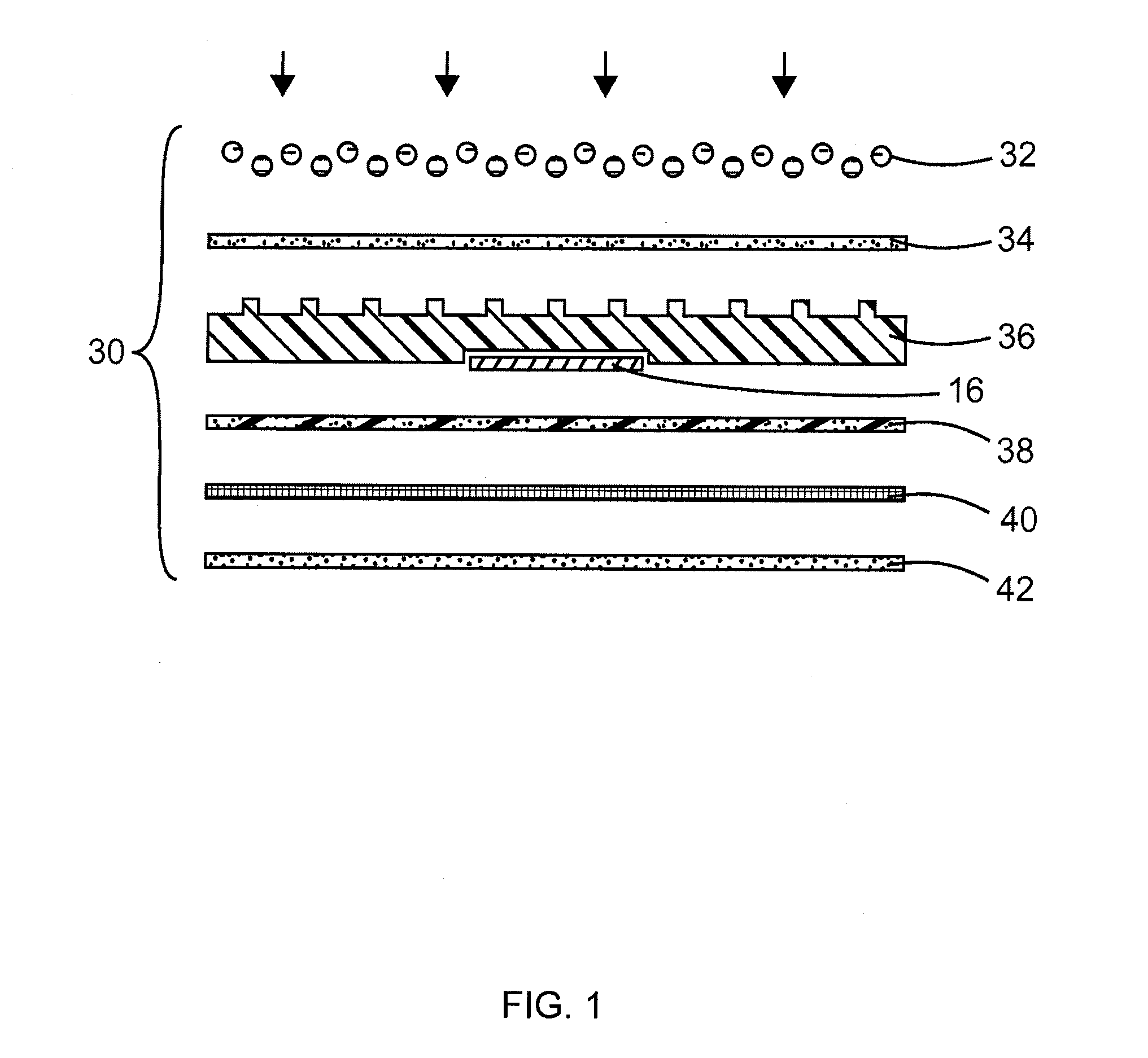
[0094]As described above and as illustrated in the figures, a first layer is a layer of glass beads. The glass beads are adhered to a textured rubber base 36 by a layer of adhesive. Inside the textured rubber base 36 there is a recess for receiving an RFID tag. The RFID tag is then held in place by a fiberglass netting and a layer of adhesive. The fiberglass netting also provides strength to the pavement marking material. Lastly, there is a layer of adhesive for adhering the pavement marking material to a road. Alternatively, the layer of glass beads and layer of adhesive may be substituted with Diamond Grade™ High Intensity Prismatic Sheeting, Series 3930, commercially available from 3M Company based in St. Paul.

[0095]In certain embodiments, a raised pavement marking material is employed that includes a top surface and a bottom surface opposite the top surface, two opposing angled side surfaces adjacent the top surface and bottom surface, with such surfaces being suitable for a mag...


PUM


Abstract

A method and system for facilitating cost effective, reliable, system redundant, self-driving vehicles involves the employment of specialized lane marking components that permit unprecedented sensor feedback, and in particular, a system and method that enables accurate lane marking recognition despite adverse weather conditions, which presently pose problems experienced by self-driving systems that rely upon vision based camera systems.

Description

RELATED APPLICATION[0001]This application seeks priority from U.S. Provisional Patent Application No. 62 / 078,539, filed on Nov. 12, 2014, and U.S. Provisional Patent Application No. 62 / 163,163, filed on May 18, 2015. The entire disclosure of the prior applications is considered to be part of the disclosure of the accompanying application and is hereby incorporated by reference.FIELD OF THE INVENTION[0002]A method and system for facilitating cost effective, reliable, system redundant, self-driving vehicles involves the employment of specialized lane marking components that permit unprecedented sensor feedback, and in particular, a system and method that enables accurate lane marking recognition despite adverse weather conditions, which presently pose problems experienced by self-driving systems that rely upon vision based camera systems.BACKGROUND OF THE INVENTION[0003]Worldwide, over a million people die on roads every year. More than 40% of fatal crashes in the U.S. involve alcohol...

Claims


Application Information

Patent Timeline
Patent Type & Authority Applications(United States)
IPC IPC(8): G06K7/10E01C11/00G05D1/02E01F9/00G01S19/13E01C9/00E01F11/00
CPCG06K7/10376E01C9/00E01C11/00G05D1/0259E01F9/005G01S19/13E01F11/00G05D2201/0213E01F9/30E01F9/578G05D1/0261Y02T10/70Y02T10/7072Y02T90/12
Inventor KOVARIK, JOSEPH E.KOVARIK, JAMES J.
Owner KOVARIK JOSEPH E
Why Eureka
Try Eureka