Eureka AIR delivers breakthrough ideas for toughest innovation challenges, trusted by R&D personnel around the world.

Actuator with transmission element

a technology of transmission element and actuator, which is applied in the direction of basic electric elements, electrical apparatus, and electric motors, can solve the problems of high cost of assembly, mounting and mounting the actuator, and manufacturing its individual parts, and achieves cost-effective manufacturing and assembly.

Active Publication Date: 2016-05-05
SCHAEFFLER TECH AG & CO KG
View PDF2 Cites 18 Cited by
  • Summary
  • Abstract
  • Description
  • Claims
  • Application Information

AI Technical Summary

Benefits of technology

The present invention provides an actuator that is cost-effective, easy to manufacture and assemble, and suitable for a sliding cam system. The actuator includes a magnet housing, thrust pin, plunger, and lever designed to transmit force from the plunger to the thrust pin. The lever is positioned in a way that eliminates planar contact between the thrust pin and lever, ensuring reliable and better force transmission. The actuator has a compact design that allows for a smaller armature stroke and a more compact magnet housing design. The position of the lever's support area is set in a way that allows for a transmission ratio of approximately two and includes a trough-like indentation for stable contact between the lever and plunger.

Problems solved by technology

The disadvantage of the actuator is that the stop valve and the flexible tongue are delicate and high-precision components, which makes it expensive to mount the actuator and to manufacture its individual parts.
The disadvantage of the actuator is that the additional supporting spring, the latching device and the rocker also represent a delicate and high-precision arrangement, which also makes it expensive to assemble and mount the actuator and to manufacture its individual parts.

Method used


Image

  • Actuator with transmission element
  • Actuator with transmission element
  • Actuator with transmission element

Examples


Embodiment Construction

[0022]Identical reference numerals are used for the same elements or elements having the same function. Furthermore, for the sake of clarity, only reference numerals which are necessary for describing the particular figure are shown in the individual figures. The illustrated specific embodiments only represent examples of how the actuator according to the present invention may be designed and do not represent a final limitation of the present invention.

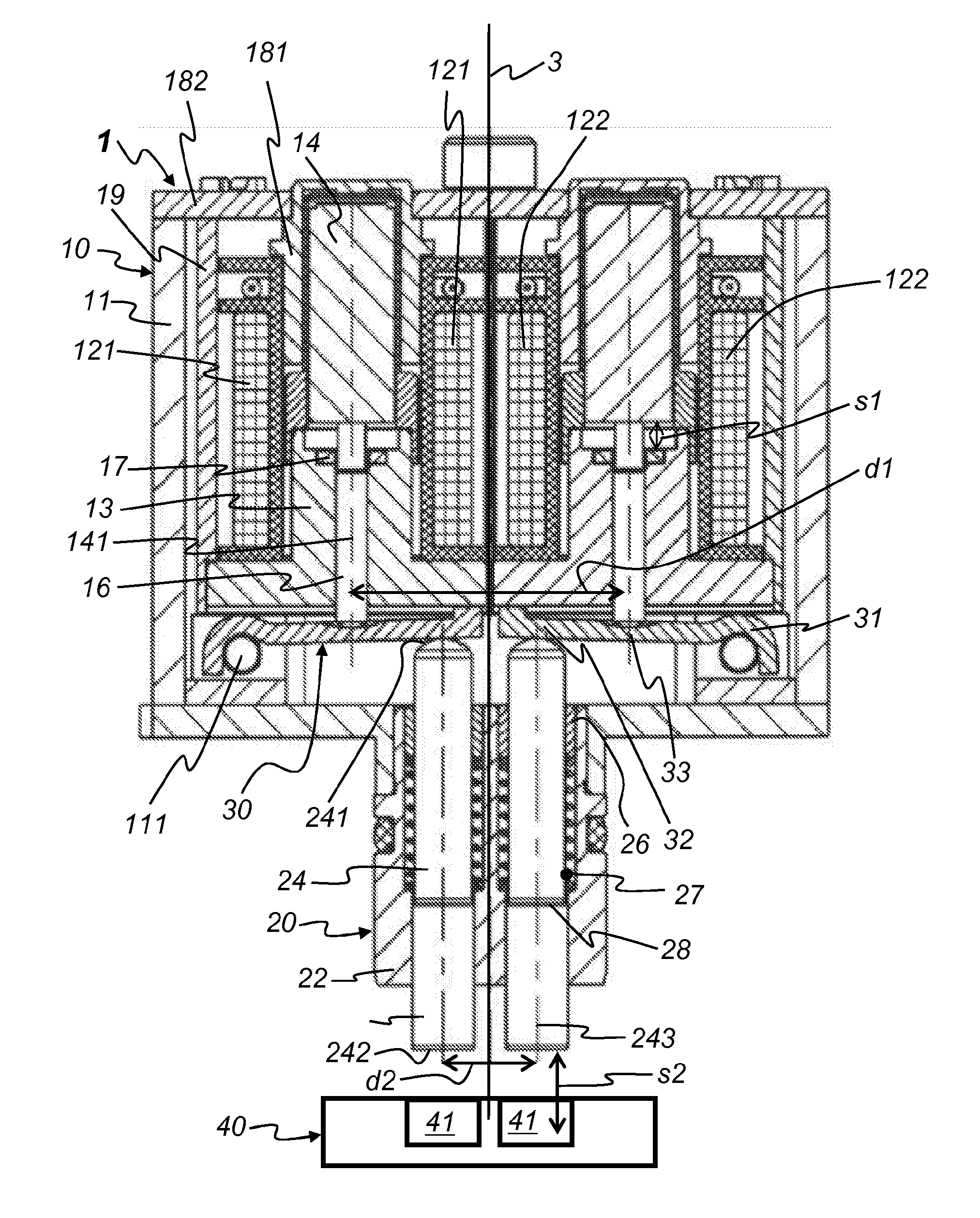
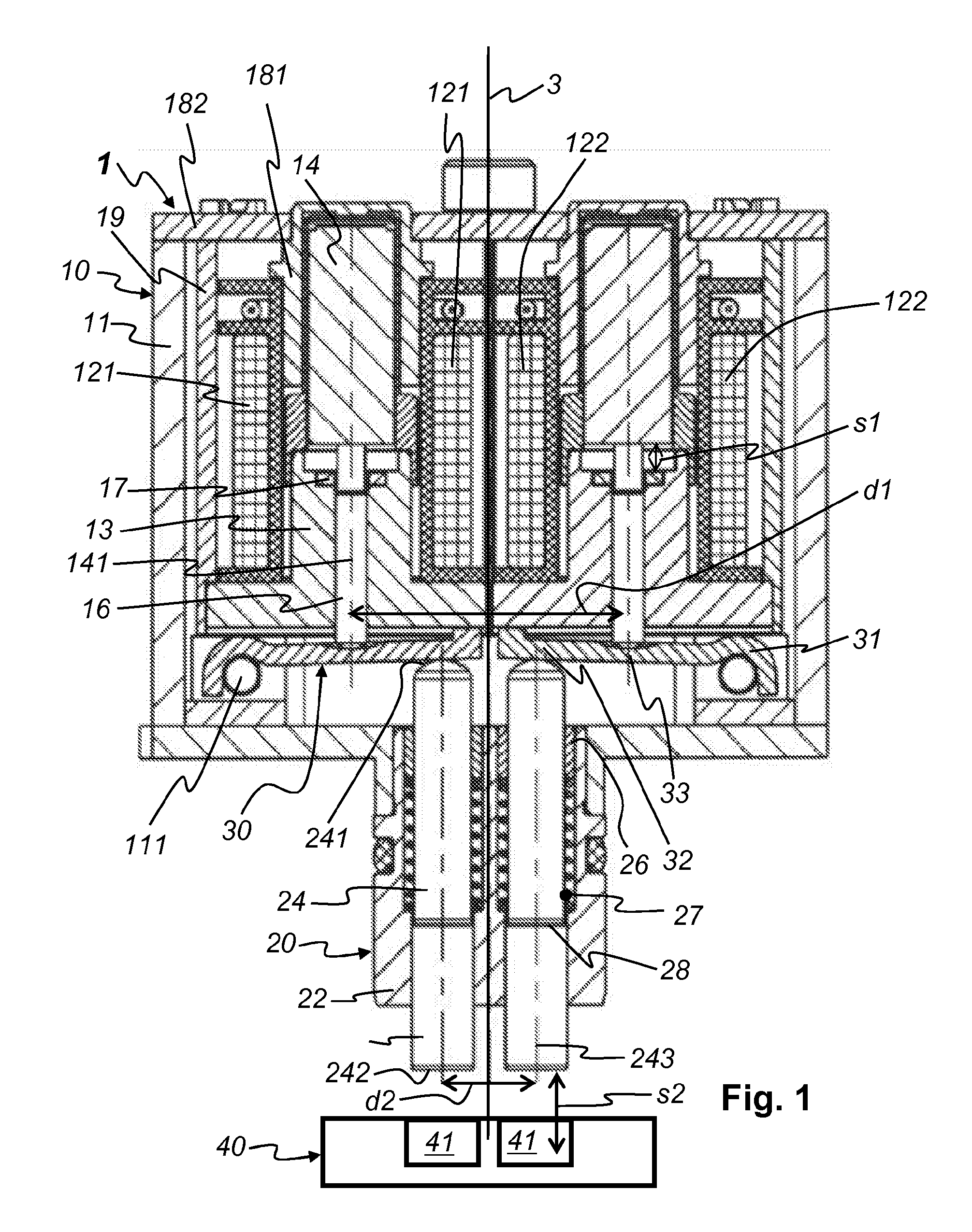
[0023]FIG. 1 shows a schematic representation of an actuator 1 according to one specific embodiment of the present invention. The actuator essentially includes an electromagnet unit 10 and a thrust pin unit 20.

[0024]Electromagnet unit 10 includes at least one electromagnet 121, 122, 13, 14, 16, 17, 181, 182, 19 and a magnet housing 11. Each electromagnet usually includes a solenoid coil 121 and 122, a magnetic yoke, which in this case is optionally designed as a unit of a yoke sleeve 181 and a yoke disk 182, an optional return path el...


PUM


Abstract

An actuator (1) including at least one electromagnet (121, 122, 13, 14, 16, 17, 181, 182, 19, a magnet housing (11), at least one thrust pin (24) and at least one movable armature (14) with a respective plunger (16) that is movable in an axial direction is provided. When the at least one electromagnet (10) is energized, an axial movement of the at least one armature (14) can be transmitted via the at least one plunger (16) to the at least one thrust pin (24). At least one lever (30) is provided which is pivotably mounted on one side in the magnet housing (11) and with which at least one plunger (16) and the at least one thrust pin (24) are operatively connected such that the axial movement of the at least one plunger (16) can be transmitted to the at least one thrust pin (24).

Description

[0001]The present invention relates to an actuator. The actuator includes at least one electromagnet, a magnet housing, at least one thrust pin and at least one movable armature having a plunger which is movable in an axial direction. When the at least one electromagnet is energized, and axial movement of the at least one armature is transmittable to the at least one thrust pin via the at least one plunger.BACKGROUND[0002]Actuators, which are also referred to as “converters,”“drive elements,” and “adjusting devices,” are known from the prior art. In particular, actuators are also known which convert electrical signals for at least one electromagnet into mechanical movement of an armature connected thereto. The armature, in turn, transmits at least part of the mechanical movement to a plunger, push rod or armature rod. The plunger (or push rod or armature rod) transmits at least part of the mechanical movement to at least one thrust pin, also referred to as a drive pin. The thrust pi...

Claims


Application Information

Patent Timeline
IPC IPC(8): H01F7/08
CPCH01F7/08F01L13/0036H01F7/1607F01L2013/0052F01L2013/101F01L2820/031H01F7/17
Inventor STRIGERWALD, MARTINHOPPE, JENSKONIAS, STEFAN
Owner SCHAEFFLER TECH AG & CO KG
Why Eureka
Eureka Blog
Learn More