Thermal optimization of an imaging scan room

a technology of thermal optimization and imaging scan room, which is applied in the direction of tomography, process and machine control, instruments, etc., can solve the problems of difficult standardization of the control of the thermal environment in such rooms to the different types of rooms, difficulty in meeting requirements, and inconvenient use of the dedicated room. achieve the effect of projecting patient comfor

Inactive Publication Date: 2016-05-05
GENERAL ELECTRIC CO
View PDF1 Cites 4 Cited by
  • Summary
  • Abstract
  • Description
  • Claims
  • Application Information

AI Technical Summary

Benefits of technology

The patent describes a computer-based method for modeling the comfort of patients in a scan room where they are being imaged. The method involves receiving information about the dimensions and shape of the scan room, the placement of the imaging system components, and the placement and operation of air supplies. A cellular mesh is generated based on this information and air flow vectors are computed for each cell in the mesh. Temperatures are then computed for each cell using the air flow vectors and boundary conditions. The resulting measure of projected patient comfort is displayed as a factor in evaluating the layout of the scan room. The method can also be used in a user interface to allow for drag-and-drop placement and orientation of the imaging system components.

Problems solved by technology

In general, the layout and size of these dedicated rooms is not uniform and may in fact vary considerably both within and between facilities.
As a result, the control of the thermal environment in such rooms may be difficult to standardize to the differing types of rooms in which imaging systems may be housed.
However, due to the layout or size of this room, these requirements may be difficult to meet when the imaging system is in operation.
Alternatively, the measures needed to meet the thermal requirements for the imaging system within a given room may result in an uncomfortable environment for patients within the room during an examination.
Thus, situations may arise where the imaging system is properly cooled but the patient is uncomfortable (e.g., cold), the patient is comfortable but the imaging system is improperly cooled, or, in the worst case, the imaging system is improperly cooled and the patient is uncomfortable.

Method used


Image

  • Thermal optimization of an imaging scan room
  • Thermal optimization of an imaging scan room
  • Thermal optimization of an imaging scan room

Examples


Embodiment Construction

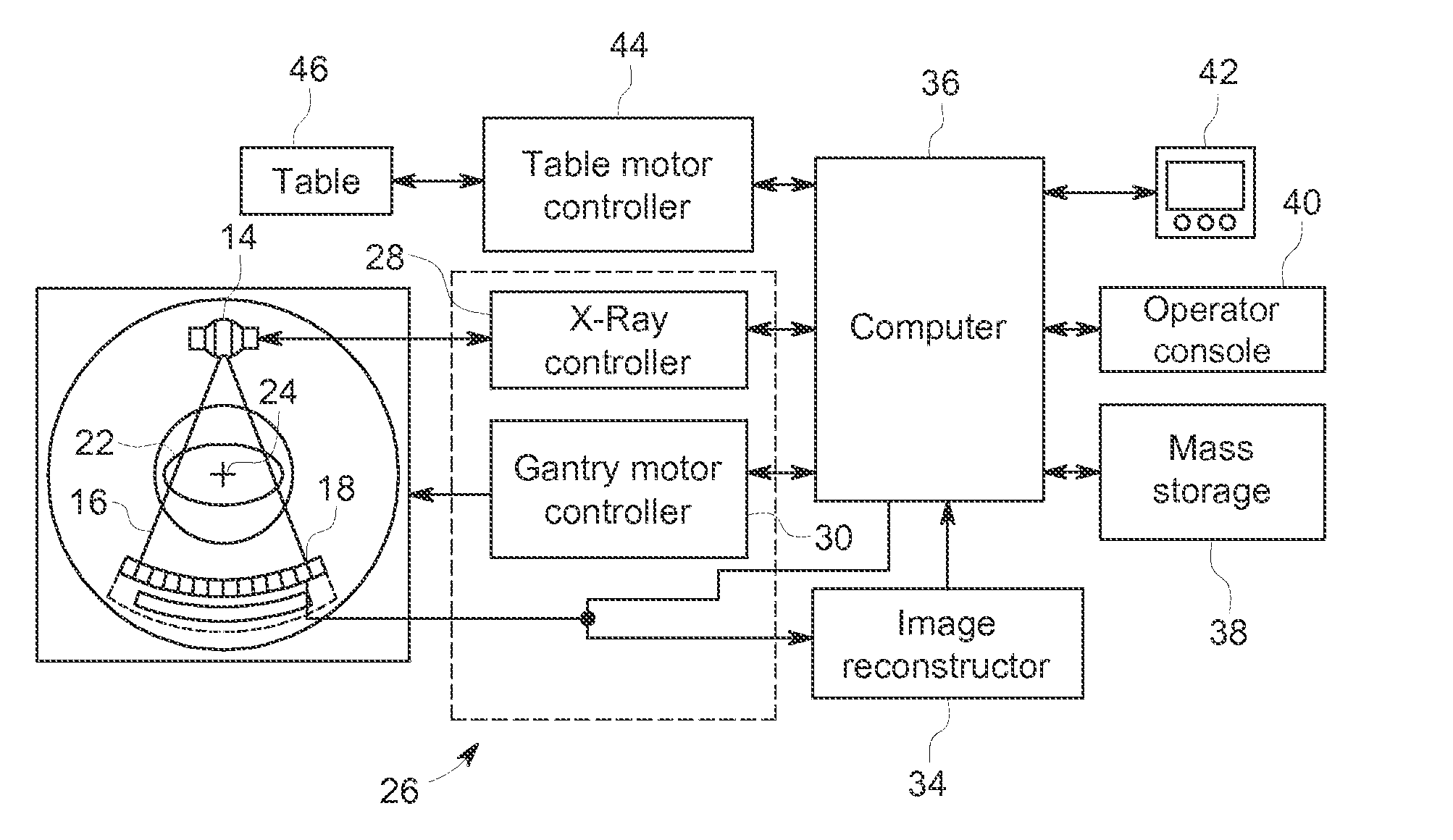
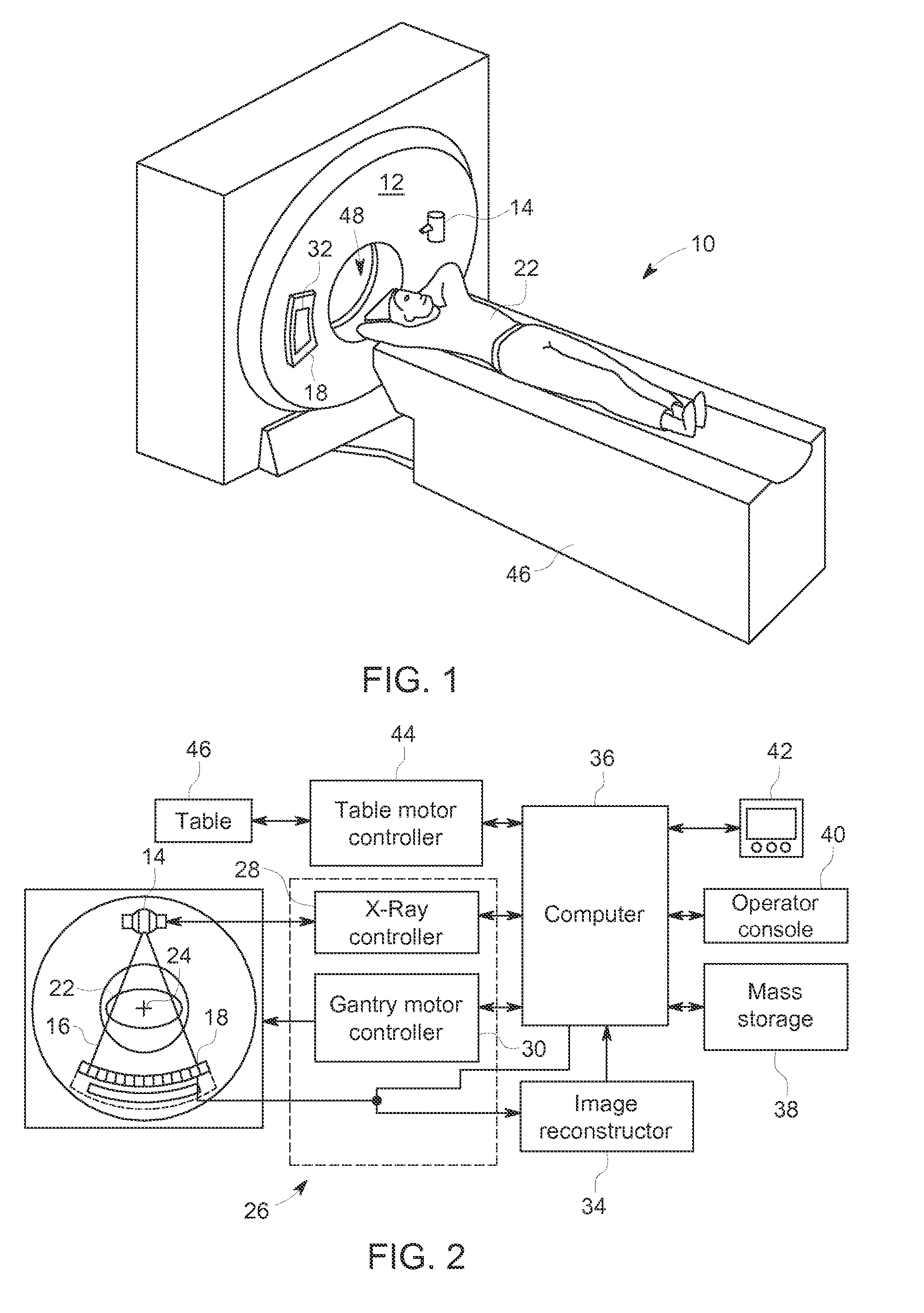
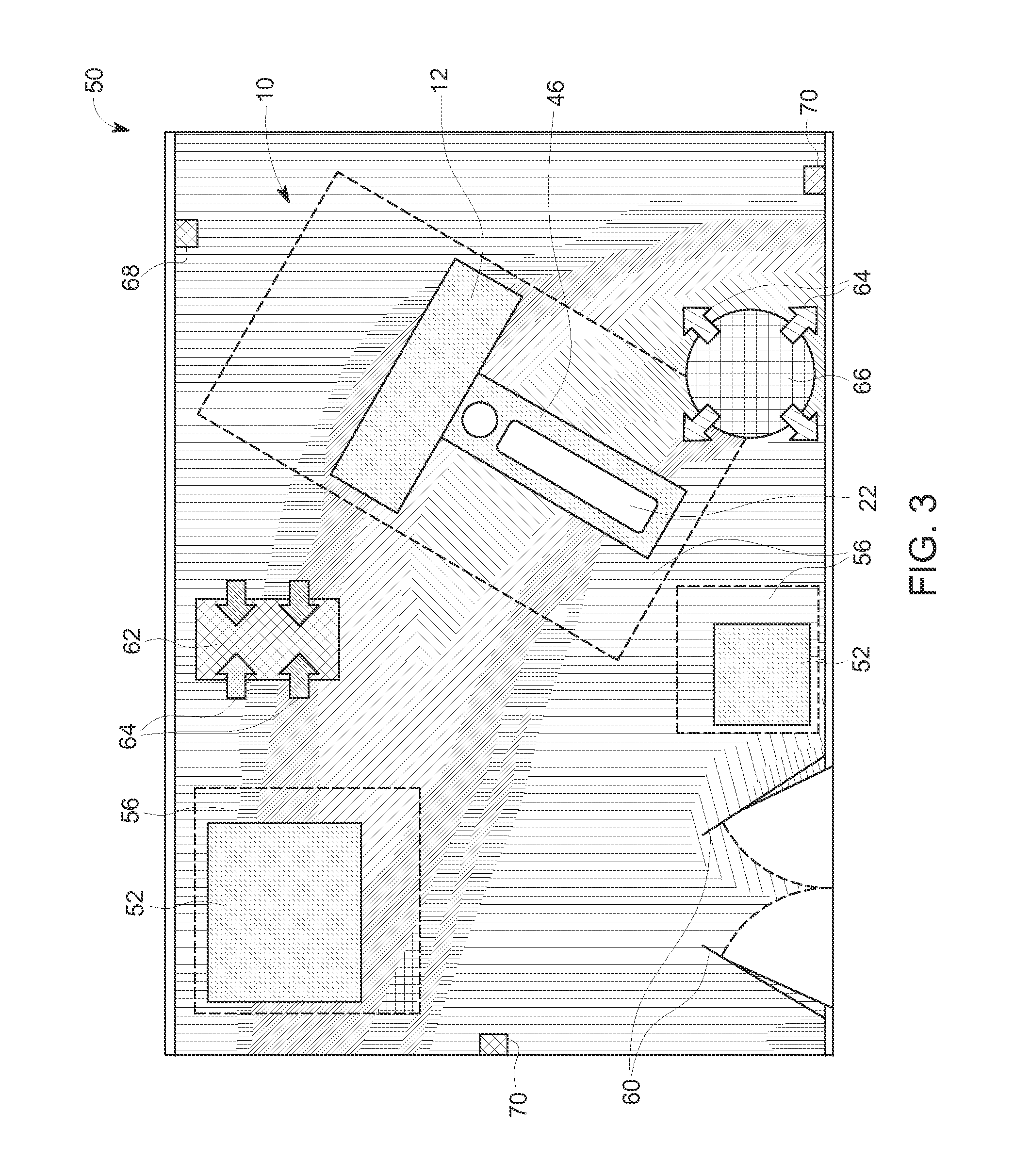
[0019]The present disclosure relates approaches for modeling environmental conditions within an environment in which an imaging system is deployed. In this approach, different sizes and layouts of rooms may be modeled as well as different types of imaging system and environmental and ventilation schemes. A user may model different position and orientation of the imaging system within the room as well as different placement and usage of ventilation and temperature control within the room. Based on the modeling, the user may generate a suitable temperature control scheme and implement such a scheme so as to adequately cool the imaging system within the room while providing a comfortable patient environment. For example, in certain implementations a detailed three-dimensional representation of the thermal and system performance consequences of a proposed system and room layout may be generated for evaluation by a user.

[0020]As will be appreciated, the present approach may be suitable f...


PUM


Abstract

In accordance with the present disclosure, a tool for evaluating the thermal layout of a scan room is discussed. In practice, the tool may be used to quickly generate and test different room and imaging system layouts to identify a suitable layout. A scan room and imaging system may then be placed and oriented in accordance with the layout that has been tested and found acceptable using the tool.

Description

BACKGROUND[0001]Embodiments of the invention generally relate to approaches for managing the thermal environment in a room or facility in which imaging devices are employed.[0002]In a medical context, imaging systems (such as general radiography X-ray system, tomosynthesis system, computed tomography (CT) system, mammography system, C-arm angiography system, single photon emission computed tomography (SPECT) system, positron emission tomography (PET) system, ultrasonic imaging system, magnetic resonance imaging (MRI) system, nuclear medicine imaging system, and various other modalities) create images of a patient or object using a variety of physical principles. For example, certain such physical principles may relate to the differential transmission of radiation (e.g., X-rays) through the body, the transmission of acoustic waves through the body, the paramagnetic properties of the body, or the localization of and breakdown of radiopharmaceuticals in the body. Images generated using...

Claims


Application Information

Patent Timeline
Patent Type & Authority Applications(United States)
IPC IPC(8): G05B17/02G06F17/50G06K9/20G06F3/0486G06F3/0481G06F3/0484A61B19/00G06F17/16
CPCG05B17/02A61B19/5225G06F17/5009G06F17/16G06F3/0486A61B2019/5276G06F3/04842G06K9/2054A61B2019/5236A61B2019/5242G06F3/0481A61B90/37A61B2090/374A61B2090/3764A61B2090/378G06F30/13G06F2119/08
Inventor MANDRUSIAK, GARY DWAYNE
Owner GENERAL ELECTRIC CO
Why Eureka
Try Eureka