
Braided textile sleeve with self-sustaining expanded and contracted states and method of construction thereof

a textile sleeve and self-sustaining technology, applied in the field of textile sleeves, can solve the problems of complicated installation of the sleeve over the elongated member, complicated installation of the sleeve, and relatively long length of the sleeve, so as to achieve the effect of increasing diameter, reducing length, and increasing length

Active Publication Date: 2016-05-05
FEDERAL MOGUL POWERTAIN LLC
View PDF14 Cites 24 Cited by
  • Summary
  • Abstract
  • Description
  • Claims
  • Application Information

AI Technical Summary

Benefits of technology

The invention is about a protective textile sleeve that can be used to enclose and protect components. The sleeve has a braided wall made of heat-set yarns that can be expanded or contracted to fit different needs. The yarns can be twisted together and braided in bundles, which can include both heat-set and non-heat-set yarns. The bundle creates a snug fit and provides resistance to high temperatures and oxidation. The sleeve can be easily inserted and removed from its protection position, and it can also be expanded or contracted as needed. Overall, this invention provides a versatile and effective way to protect components in high-temperature environments.

Problems solved by technology

Namely, the ability to manually increase the diameter of the braided sleeve requires applying a continual, externally applied compression force during installation, which can prove challenging, and thus, can complicate the ability of the installer to readily install the sleeve over the elongate member.
Further complicating installation of a braided sleeve arises when the sleeve has a relatively long length.
With the sleeve having a relatively long length, difficultly arises by having to axially compress the opposite ends toward one another without causing the sleeve to fold or buckle along the length of the sleeve.
As such, the effective length of the sleeve can be unintentionally decreased.

Method used


Image

  • Braided textile sleeve with self-sustaining expanded and contracted states and method of construction thereof
  • Braided textile sleeve with self-sustaining expanded and contracted states and method of construction thereof
  • Braided textile sleeve with self-sustaining expanded and contracted states and method of construction thereof

Examples


Embodiment Construction

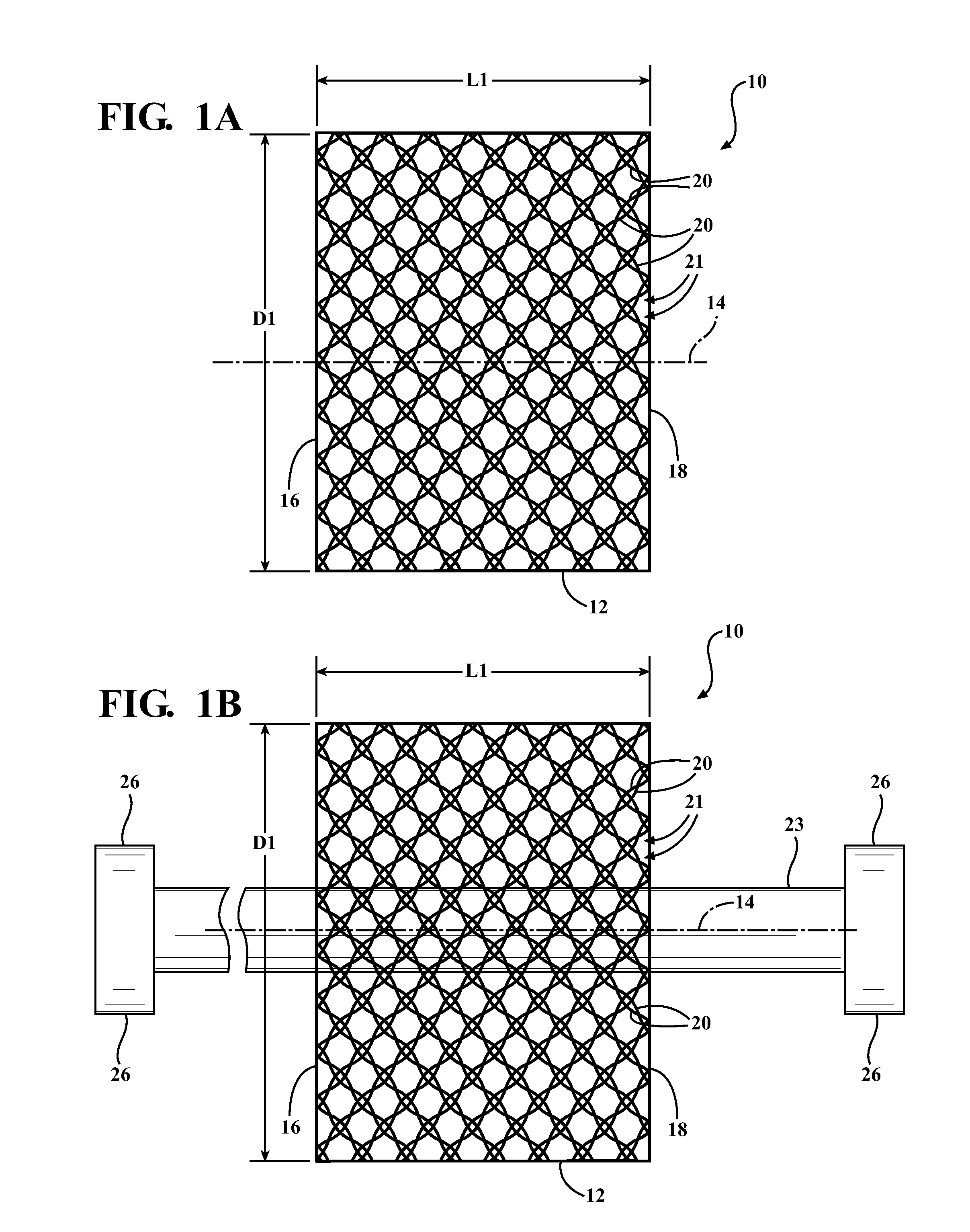
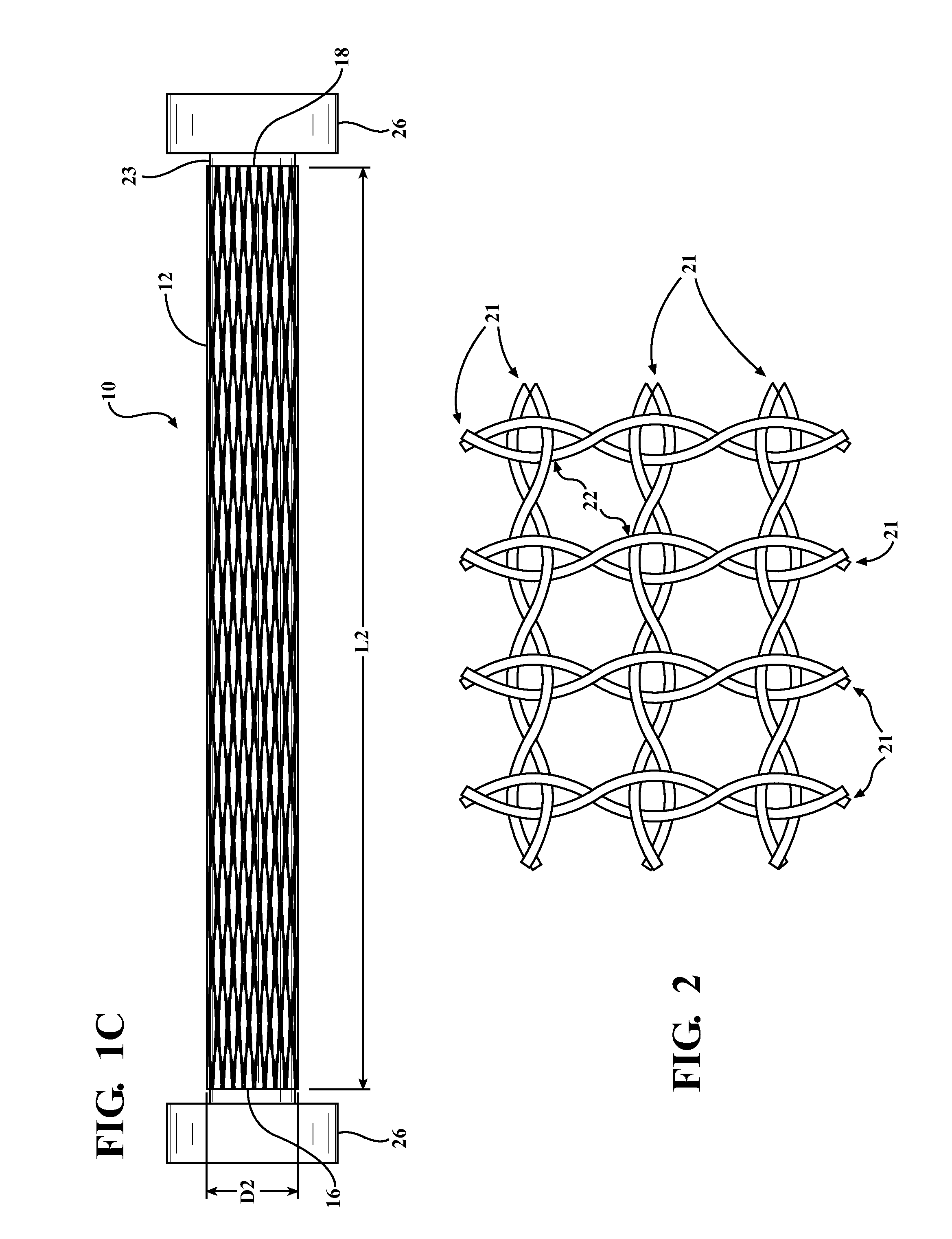
[0030]Referring in more detail to the drawings, FIGS. 1A-1C illustrate a braided protective textile sleeve, referred to hereafter as sleeve 10, constructed in accordance with one aspect of the invention. The sleeve 10 has a braided, circumferentially continuous, seamless tubular wall 12 extending lengthwise along a central longitudinal axis 14 between opposite ends 16, 18, wherein one or both of the ends 16, 18 can be formed as an open or closed end, shown as both being open ends 16, 18. The wall 12 is axially compressible to attain a pre-assembled first state, having a decreased length L1 and increased diameter D1 (FIGS. 1A and 1B) and is axially extendible to attain a fully assembled second state, having an increased length L2 and decreased diameter D2 (FIG. 1C). The wall 12 includes heat-settable, braided yarn 20, which upon being heat-set, imparts a bias on the wall 12. The bias imparted by the heat-set yarn 20 causes at least a portion of the wall 12 to remain in a selected one...


PUM

PropertyMeasurementUnit
Diameteraaaaaaaaaa
Lengthaaaaaaaaaa
Heataaaaaaaaaa

Abstract

A protective textile sleeve includes a braided, tubular wall extending lengthwise along a central longitudinal axis between opposite ends. The wall has a decreased length, increased diameter first state and an increased length, decreased diameter second state. Heat-set, braided yarns within the wall impart a bias on the wall, wherein the bias causes the first and second states to be bi-stable and self-sustaining.

Description

CROSS-REFERENCE TO RELATED APPLICATION[0001]This application claims the benefit of U.S. Provisional Application Ser. No. 62 / 072,890, filed Oct. 30, 2014, which is incorporated herein by reference in its entirety.BACKGROUND OF THE INVENTION[0002]1. Technical Field[0003]This invention relates generally to textile sleeves, and more particularly to braided textile sleeves.[0004]2. Related Art[0005]It is known to protect elongate members in textile sleeves against a variety of environmental conditions and affects, or to just contain elongate members in textile sleeves for bundling and routing purposes, such as in knit, woven or braided sleeves. In the case of braided sleeves, the braided wall is commonly braided as a circumferentially continuous, seamless wall, sometimes referred to as a ‘closed’ wall. One known advantage of a closed, braided wall construction is that the wall can be circumferentially expanded to facilitate sliding the wall over an elongated member by manually pushing an...

Claims


Application Information

Patent Timeline
IPC IPC(8): D04C1/06B29C35/02B29B11/14B29B11/04D04C1/02B29C55/24
CPCD04C1/06D04C1/02B29C55/24B29B11/14B29L2023/001B29C35/02B29K2101/10B29K2105/258B29B11/04D04C3/40D10B2505/12D10B2401/046B29C49/071B29C2949/0715
Inventor FATHALLAH, AMELPANEA, ANA MARIA
Owner FEDERAL MOGUL POWERTAIN LLC
Learn More