Fixture for a vehicle

a technology for fixings and vehicles, applied in the field of fixings for vehicles, can solve the problems of deteriorating riding comfort, conventional fixtures vulnerable to twisting, and the external force applied to the indoor handle may not be uniformly distributed to the retaining arms

Inactive Publication Date: 2016-04-28
DAEHAN SOLUTION
View PDF0 Cites 3 Cited by
  • Summary
  • Abstract
  • Description
  • Claims
  • Application Information

AI Technical Summary

Benefits of technology

[0021]The present invention is directed to a fixture for a vehicle, which is configured so that three retaining arms inserted into and caught by a coupling hole formed in a body panel are inserted into and caught by the coupling hole to be spaced at regular intervals from each other, and arranged in the form of a triangular pyramid so as to absorb an external force, even though the external force is applied in any directions, thereby being easily assembled, and which is capable of dispersing and absorbing twisting generated when an indoor handle installed using the fixture is used, and thus being prevented from escaping from or being separated from the coupling hole.
[0022]Also, the present invention is directed to a fixture for a vehicle, which is configured to be manufactured by a press processing, thereby having a simple structure to be easily manufactured and used at a low manufacturing cost, and also being massively manufactured to increase productivity.

Problems solved by technology

(1) The conventional fixtures (clip modules) have a structure which is not moved once they are fixed. For example, in case of a room lamp, a head lamp, and a headliner, since they are not moved and an external force is hardly applied to them, there is no problem. However, when the indoor handle which is grasped by a passenger and to which an external force is applied is fixed, there are some problems as follows.
(2) Since the fixture is manufactured so the retaining arms substantially serving as hooks are located to face each other and to be symmetrical vertically or horizontally, the external force applied to the indoor handle may not be uniformly dispersed to the retaining arms.
(3) That is, when the external force is applied in a direction in which an auxiliary handle is grasped and pulled downward, the external force is uniformly applied to the conventional fixture and thus the retaining arms. However, when the auxiliary handle is twisted or grasped to be inclined to one side, the conventional fixture is twisted by a force generated at this time, and thus the retaining arms are also twisted.
(4) In the retaining arms twisted as described above, the force is applied to one of the retaining arms or to one side, and thus the twisted retaining arms may be separated from or may escape from a coupling hole.
(5) This is caused by a structure in which the force applied to the indoor handle may not be dispersed to each retaining arm, even when being applied in any directions, i.e., a structure in which the retaining arms face each other.
(6) Meanwhile, the conventional fixture which is vulnerable to the twisting may be separated from or may escape from the coupling hole, when the indoor handle is used.
(7) When the fixture is separated, the fixture may bump against other construction elements and may generate noise, and thus the separation of the fixture may act as a factor which deteriorates riding comfort.
(8) The indoor handle is generally fixed by two fixtures, and when all of the fixtures are separated from the coupling hole, the indoor handle may fall into an interior of the vehicle, and thus a safety accident may occur.

Method used


Image

  • Fixture for a vehicle
  • Fixture for a vehicle
  • Fixture for a vehicle

Examples


Embodiment Construction

[0035]Preferred embodiments of the present invention will be described in detail below with reference to the accompanying drawings. It should be understood that the terms used in the specification and the appended claims should not be construed as limited to general and dictionary meanings, but interpreted based on the meanings and concepts corresponding to technical aspects of the present invention on the basis of the principle that the inventor is allowed to define terms appropriately for the best explanation.

[0036]Therefore, the description proposed herein is just a preferable example for the purpose of illustrations only, not intended to limit the scope of the invention, so it should be understood that other equivalents and modifications could be made thereto without departing from the spirit and scope of the invention.

[0037](Construction)

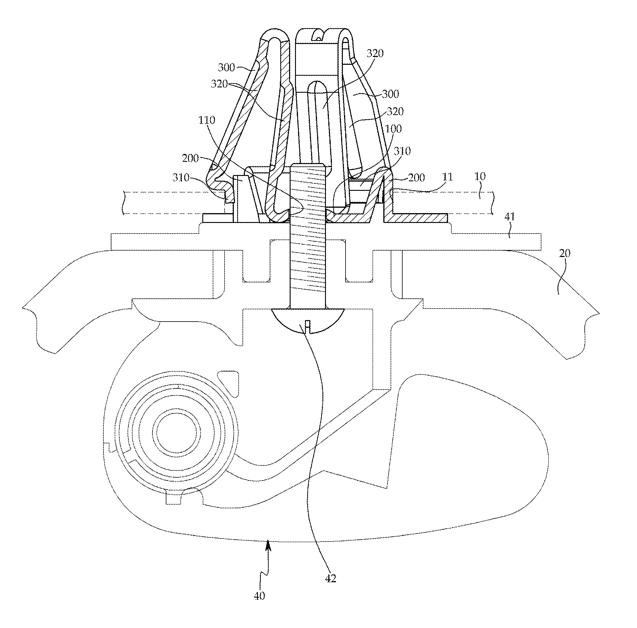
[0038]As illustrated in FIGS. 4 to 7, a fixture for a vehicle according to the present invention includes a base 100 formed in a circular shap...


PUM


Abstract

A fixture for a vehicle, which is configured so that three retaining arms inserted into and caught by a coupling hole formed in a body panel are inserted into and caught by the coupling hole to be spaced at regular intervals from each other, and arranged in the form of a triangular pyramid so as to absorb an external force, even though the external force is applied in any directions, thereby being easily assembled, and which is capable of dispersing and absorb twisting generated when an indoor handle installed using the fixture is used, and thus being prevented from escaping from or being separated from the coupling hole.

Description

CROSS-REFERENCE TO RELATED APPLICATION[0001]This application claims priority to and the benefit of Korean Patent Application No. 10-2014-0145433, filed on Oct. 24, 2014, the disclosure of which is incorporated herein by reference in its entirety.BACKGROUND[0002]1. Field of the Invention[0003]The present invention relates to a fixture for a vehicle, and more particularly, to a fixture for a vehicle, in which a plurality of retaining arms substantially serving as stoppers are arranged in the form of a pyramid so that an external force transmitted from an outer side to, for example, an indoor handle is equally dispersed to each retaining arm, and the fixture is prevented from being escaped or separated from a coupling hole formed in a body panel, and thus noise is reduced, and a safety accident generated when the indoor handle falls into an interior of the vehicle is prevented.[0004]2. Discussion of Related Art[0005]Generally, various construction elements are assembled in a vehicle us...

Claims


Application Information

Patent Timeline
Patent Type & Authority Applications(United States)
IPC IPC(8): F16B21/20E05B85/12F16B2/24B60Q3/02
CPCF16B21/20F16B2/241E05B85/12B60Q3/0203B60N3/026E05B79/06F16B2/243F16B5/065F16B37/043
Inventor KWON, CHOONG HO
Owner DAEHAN SOLUTION
Why Eureka
Try Eureka