
Baler and method for improved bale handling

a baler and bale technology, applied in the field of balers, can solve the problems of limiting the total number of knotters, affecting the production efficiency of balers, and affecting the operation and maintenance of balers,

Inactive Publication Date: 2016-04-28
DEERE & CO
View PDF11 Cites 30 Cited by
  • Summary
  • Abstract
  • Description
  • Claims
  • Application Information

AI Technical Summary

Benefits of technology

The patent describes a baler and method for making bales of crop material. The baler has a baling chamber and a crop-moving device for compressing the crop material into a bale. A sheet of wrap material is then wrapped around a frame to form a sleeve around the bale. The bale is then ejected from the baling chamber and moved through the wrap frame to be wrapped. The baler may have one or more bale chutes and a moveable rear wall to compress the crop material. The baler may also have a side member that moves laterally within the baling chamber to eject the bales onto the chutes. The technical effects of this patent include improved efficiency and control over the baling process, as well as improved protection and preservation of the crop material during storage and transportation.

Problems solved by technology

Various issues may arise for known balers, as the balers handle (e.g., form, wrap, and eject) bales.
Among these issues, the complexity, size, and weight of various knotters may complicate baler manufacturing, operation, and maintenance.
For example, the relatively large size of typical knotters may limit the total number of knotters that may be provided for a given baling chamber.
Because known knotters are typically configured to tie only one loop of twine at a time, the number of twine loops for tying bales from a given baling chamber may be limited accordingly.
Further, because of the complexity of typical knotters, the knotters may also be subject to frequent breakage or damage.
This may result in incomplete or inadequate tying of finished bales as well as significant down-time and maintenance expense for the affected baler.

Method used


Image

  • Baler and method for improved bale handling
  • Baler and method for improved bale handling
  • Baler and method for improved bale handling

Examples


Embodiment Construction

[0024]The following describes one or more example embodiments of the disclosed baler and related method, as shown in the accompanying figures of the drawings described briefly above. Various modifications to the example embodiments may be contemplated by one of skill in the art, including implementation of the disclosed method through a special-purpose computing system employing one or more processor devices and memory architectures.

[0025]As used herein, “wrap material” may indicate one of various types of materials utilized to hold bales of compressed plant matter together or to otherwise maintain the integrity (structural or otherwise) of the bales. Wrap material may include, for example, twine or similar material, net wrap, plastic or other sheeting (i.e., “sheet wrap”), banding, straps, composite rolls with various layers of vapor permeable, liquid impermeable, and other materials, and so on. In certain instances, wrap material may be provided in spools or rolls, including spool...


PUM


Abstract

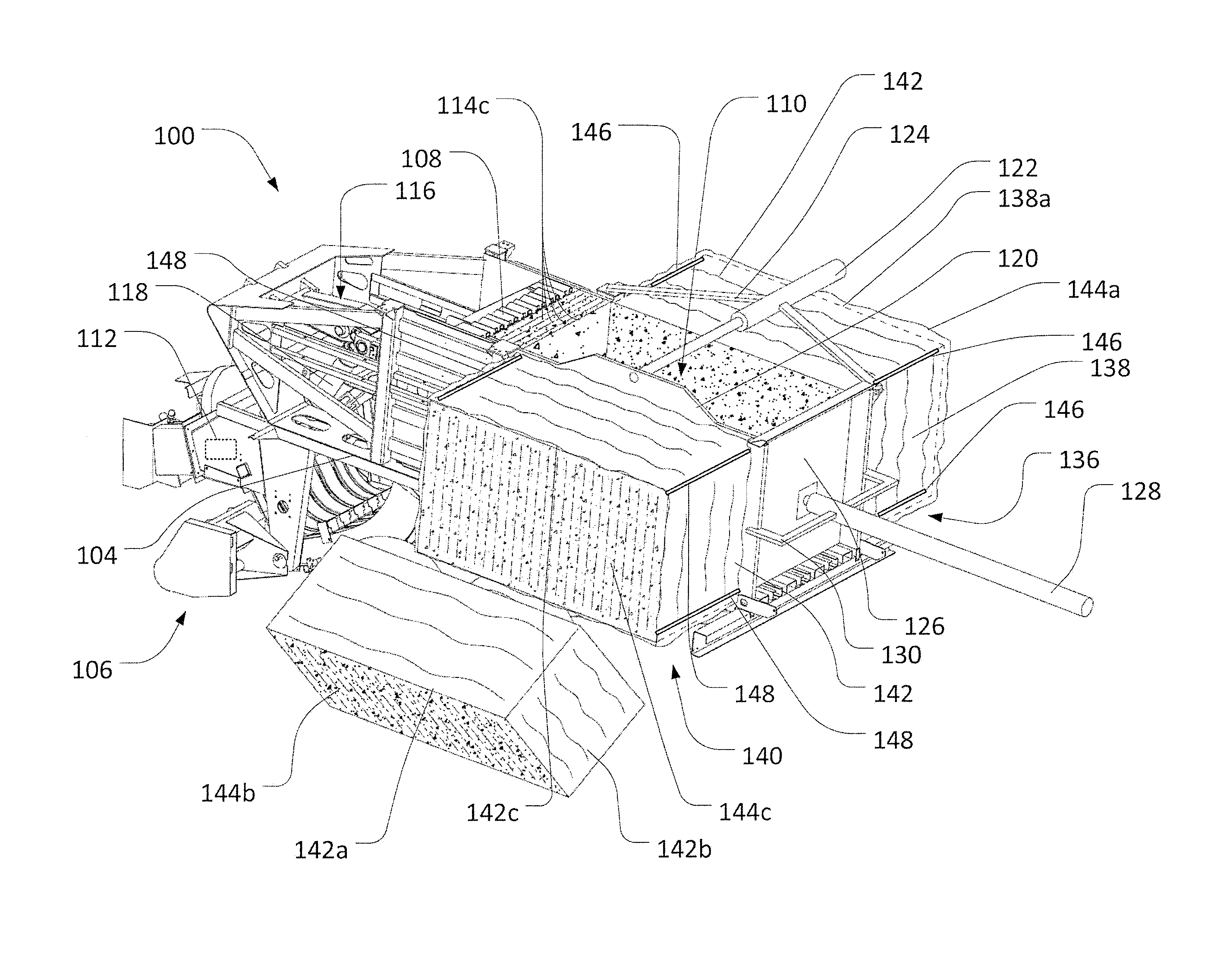
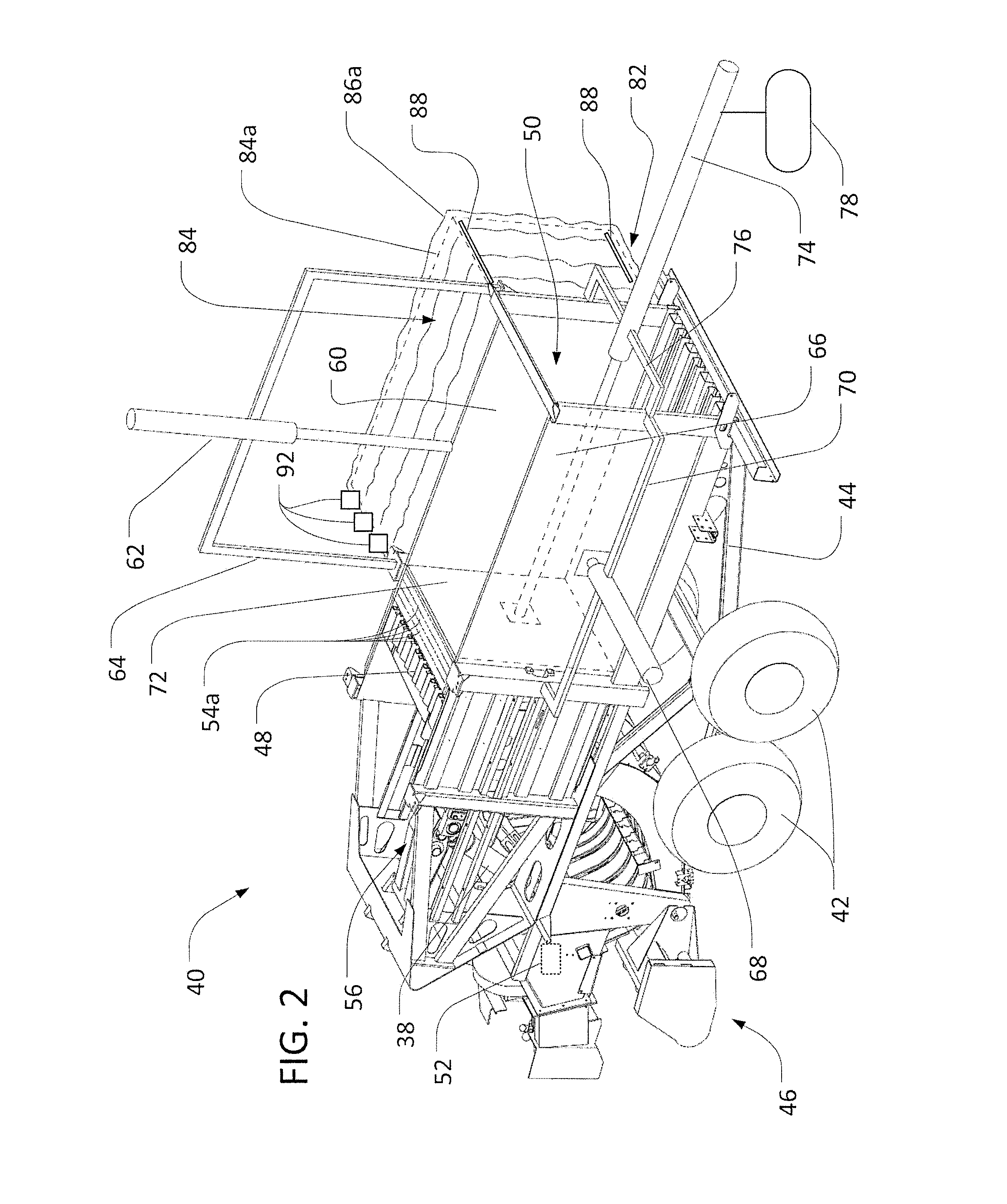
A baler and method are described for forming and wrapping bales of crop material. A baler may include a baling chamber, a crop-moving device for compressing crop material into a bale within the baling chamber, a bale chute oriented outside the baling chamber, and a wrap frame supported by the bale chute. Once formed within the baling chamber, the bales may be ejected from the baling chamber to the bale chute. A sheet of wrap material may be wrapped about the wrap frame, such that a sleeve of wrap material is formed from the sheet. The bale may be moved through the wrap frame, such that the bale engages the sleeve to pull the sleeve from the wrap frame and the bale is wrapped by the sleeve.

Description

CROSS-REFERENCE TO RELATED APPLICATION(S)[0001]Not applicable.STATEMENT OF FEDERALLY SPONSORED RESEARCH OR DEVELOPMENT[0002]Not applicable.FIELD OF THE DISCLOSURE[0003]This disclosure relates to balers, including the formation, wrapping, and tying of finished bales.BACKGROUND OF THE DISCLOSURE[0004]In various agricultural and other settings, it may be useful to form bales from crop (or other plant) material, such as hay or corn stover. Various machines or mechanisms may be utilized to gather material (e.g., from a windrow along a field) and process it into bales. The formed bales may have various sizes and, in certain applications, may exhibit generally rectangular (i.e., or other) cross-sections. In order to create rectangular bales, for example, a square baler may travel along a windrow of cut crop material gathering the material into a baling chamber. A reciprocating plunger or other mechanisms may then compress the crop material into bales.[0005]Known balers may include various ...

Claims


Application Information

Patent Timeline
IPC IPC(8): A01F15/08A01F15/14A01F15/04
CPCA01F15/0875A01F15/145A01F15/042A01F15/0705B30B9/3007A01F15/071A01F2015/0735
Inventor KRAUS, TIMOTHY J.
Owner DEERE & CO
Learn More