
Devices, systems, and methods for repairing soft tissue and attaching soft tissue to bone

a soft tissue and bone technology, applied in the field of soft tissue repair sites, can solve the problems of affecting the repair outcome, affecting the repair quality, and affecting the repair effect,

Active Publication Date: 2016-04-14
CONEXTIONS
View PDF7 Cites 124 Cited by
  • Summary
  • Abstract
  • Description
  • Claims
  • Application Information

AI Technical Summary

Benefits of technology

The present invention provides a soft tissue repair device that includes a plate and an anchor for repairing soft tissue at a repair site. The plate has a periphery and is positioned over the soft tissue, while the anchor has a base and at least four legs that extend from the base. The legs are moveable from a first position to a second position to repair the soft tissue. The device also includes one or more plate filaments and one or more anchor filaments that are coupled to the plate and anchor, respectively. The legs have a curved configuration that facilitates movement and can be positioned around separate portions of the plate or the anchor. The device can be used with a delivery device that includes an anvil to force the legs against the anvil buckets to move them to the curved position. The technical effects of the invention include improved soft tissue repair with reduced damage to the surrounding tissue and increased stability of the repair.

Problems solved by technology

However, the failure rate of tendon repairs is close to 30 percent, primarily because of overloading at the repair site.
While this can provide a good initial repair, the strength and quality of the repair may quickly degrade with subsequent loading and mobilization.
Although postoperative therapy may be utilized to reduce adhesion, the resulting tension can induce gap formation or tendon rupture at the repair site, seriously impairing the outcome of the repair.
Gapping at the repair site has many negative effects, such as reduced repair strength, tendon rupture, and an increased probability for adhesion.
Further, complex suture patterns are also used for fixating soft tissue, such as tendon and ligaments, to bone, resulting in similar negative effects to the patient and often result in subsequent procedures depending on the activity level of the patient.
Furthermore, such complex suturing procedures are time consuming and typically require specialized surgeons to perform such procedures.

Method used


Image

  • Devices, systems, and methods for repairing soft tissue and attaching soft tissue to bone
  • Devices, systems, and methods for repairing soft tissue and attaching soft tissue to bone
  • Devices, systems, and methods for repairing soft tissue and attaching soft tissue to bone

Examples


Embodiment Construction

[0094]Various embodiments are disclosed herein of a soft tissue repair device. Such repair device may be sized and configured to approximate and fuse, for example, a lacerated tendon. The various embodiments may provide structure that maintains two ends of a lacerated tendon in an abutting relationship, without gapping, while allowing the tendon adjacent the tendon ends and along the length of the repair device to provide controlled elongation of the tendon. In this manner, the repair device of the present invention may provide the proper healing required for fusing the tendon ends while still providing movement of the tendon to minimize atrophy and potential adhesions.

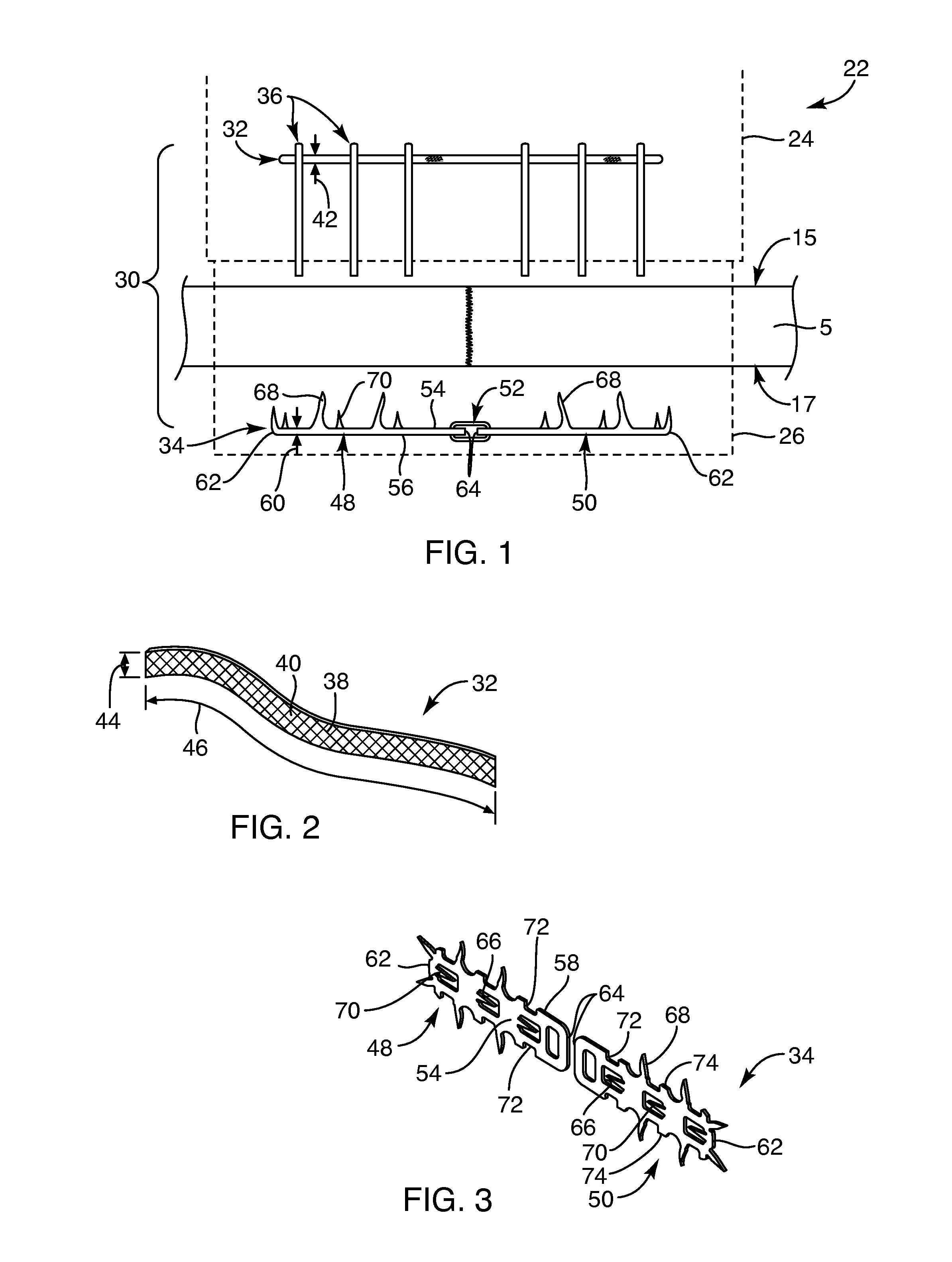
[0095]With reference to FIG. 1, one embodiment of a repair device 30, shown in a pre-deployed state, is provided. The repair device 30 may include a flexible member 32 and one or more rigid members 24 that may be coupled together with anchors 36. The flexible member 32 may be positioned relative to separate and discre...


PUM

PropertyMeasurementUnit
Angleaaaaaaaaaa
Angleaaaaaaaaaa
Lengthaaaaaaaaaa

Abstract

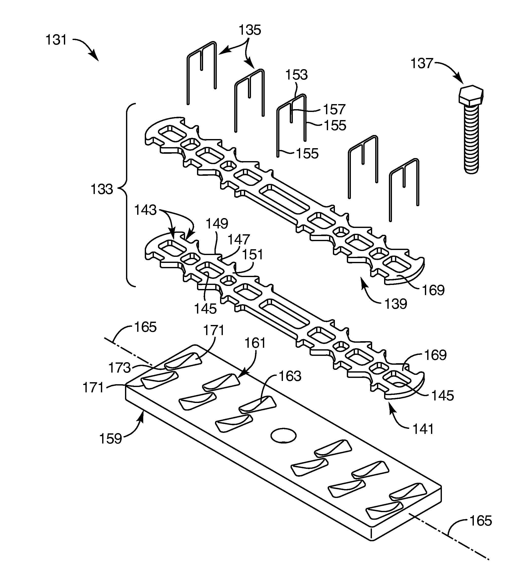
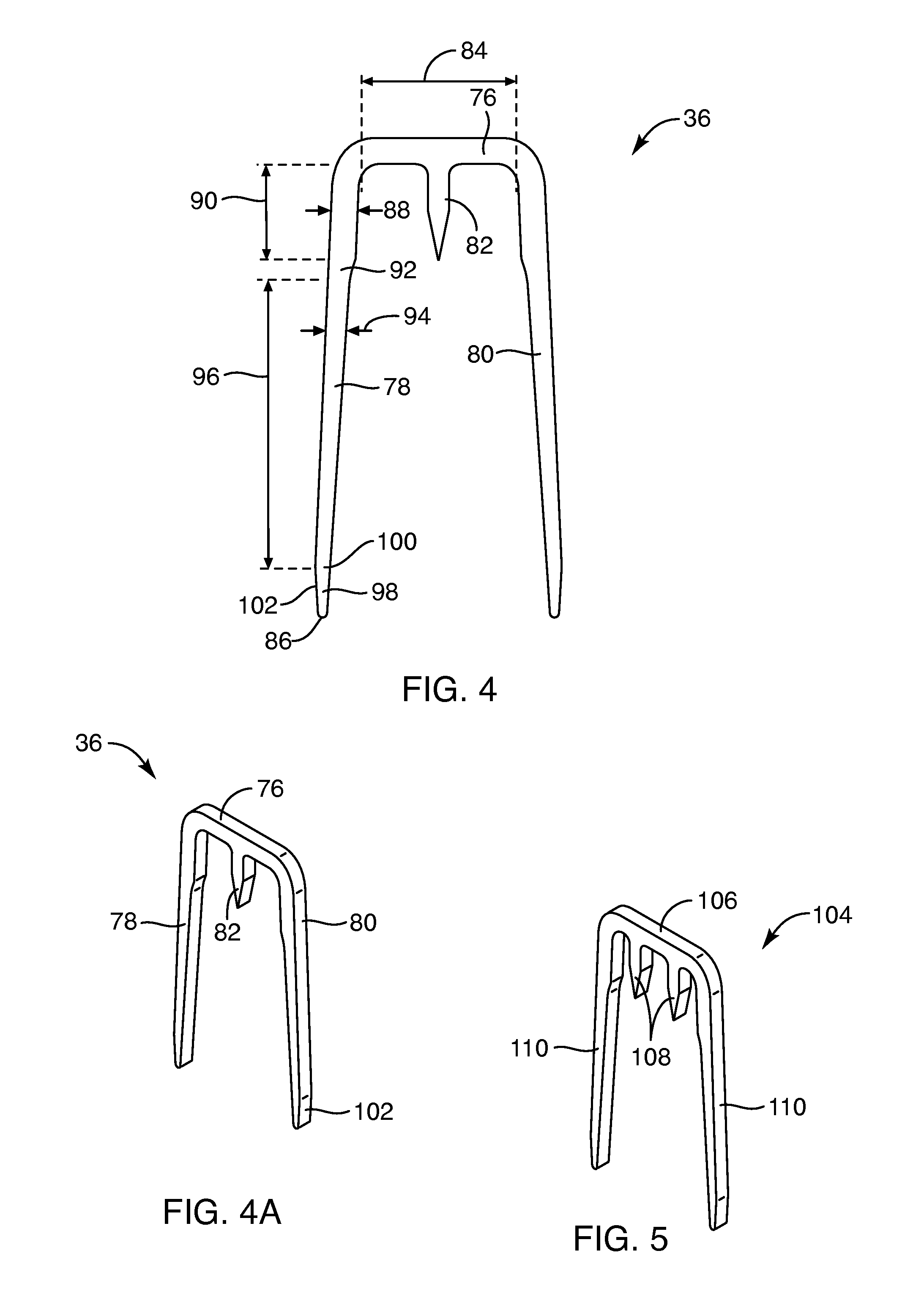
Devices, systems and / or methods for repairing soft tissue adjacent a repair site. In one embodiment, a repair device includes a plate member and an anchor. The plate member having a periphery, the plate member configured to be positioned along an outer surface of the soft tissue. The anchor includes a base and six legs extending from the base, the six legs extending from the base being moveable to a curled configuration such that the six legs wrap around separate portions of the periphery of the plate member with the soft tissue therebetween. In this manner, the repair device may be anchored to the soft tissue.

Description

CROSS-REFERENCE TO RELATED APPLICATIONS[0001]The present application claims the benefit of U.S. Provisional Application No. 62 / 215,739, filed Sep. 9, 2015, U.S. Provisional Application No. 62 / 129,742, filed Mar. 6, 2015, U.S. Provisional Application No. 62 / 094,032, filed Dec. 18, 2014, and U.S. Provisional Application No. 62 / 064,533, filed Oct. 16, 2014, the disclosures of each are hereby incorporated by reference herein in their entirety. The present application also claims the benefit, and is a continuation-in-part of, U.S. patent application Ser. No. 14 / 645,924, filed Mar. 12, 2015, which claims the benefit of U.S. Provisional Patent Application No. 62 / 053,056, filed Sep. 19, 2014, U.S. Provisional Patent Application No. 62 / 040,451, filed Aug. 22, 2014, U.S. Provisional Patent Application No. 62 / 007,783, filed Jun. 4, 2014, and U.S. Provisional Patent Application No. 61 / 952,114, filed Mar. 12, 2014, the disclosures of each are hereby incorporated by reference herein in their enti...

Claims


Application Information

Patent Timeline
IPC IPC(8): A61B17/064A61B17/068
CPCA61B17/0643A61B17/0644A61B2017/0641A61B17/0686A61B17/0642A61B17/0487A61B17/064A61B17/072A61B17/07292A61B17/08A61B17/1146A61B2017/00867A61B2017/0496A61B2017/1103A61B2017/1132A61F2/0811A61F2002/0829A61F2002/0864A61F2002/0888
Inventor LINDER, RICHARD J.KUBIAK, ERIK N.TAYLOR, ROY M.EVANS, ZACKERY K.COLE, TYLER J.MILES, SCOTT D.BECK, KENT F.
Owner CONEXTIONS
Learn More