Methods of Retrofitting Injection Molding Machines

a technology of injection molding machine and injection molding machine body, which is applied in the field of injection molding machine, can solve the problems of shortening the life of mechanical components and reducing the possibility of failure, and achieve the effect of improving the operation of the molding machin

Active Publication Date: 2016-04-07
IMFLUX INC
View PDF1 Cites 5 Cited by
  • Summary
  • Abstract
  • Description
  • Claims
  • Application Information

AI Technical Summary

Benefits of technology

[0006]However, embodiments of the present disclosure can be used to improve the operation of a molding machine by changing its original mold cycle to a retrofit mold cycle. The original mold cycle is the mold cycle used on an injection molding machine that has not yet been retrofitted with the addition of a retrofit controller to the machine. The retrofit mold cycle is the mold cycle that differs from the original mold cycle, and is used on an injection molding machine that has been retrofitted with the addition of a retrofit controller to the machine.
[0007]A retrofit mold cycle can allow an injection molding machine to use lower injection pressures, when compared with the original mold cycle. Operating at lower pressures uses less energy, reduces stress on mechanical components, and increases the safety factor for the machine. The machine can use less energy at lower pressures since its injection unit does not need to perform as much work. The reduced stress can lengthen the life of mechanical components and decrease the possibility of their failure. The machine can operate at an increased safety factor, since there will be a relatively greater difference between its operating pressures and the maximum rated pressure for the machine.
[0008]A retrofit mold cycle can also allow an injection molding machine to use more constant injection pressures, when compared with the original mold cycle. Operating at more constant pressures provides better melt flow through the mold cavity and better contact between the molten plastic and the surface of the mold cavity. Better melt flow can lead to smoother and more consistent filling, which improves the quality of the molded object. Better contact can lead to better heat-transfer between the molten plastic and the mold. Better heat transfer can ensure that plastic remains molten throughout the filling (avoiding ‘freeze-off’ problems). Better heat transfer can also provide faster cooling. Faster cooling can lead to faster mold cycle times and thus, greater throughput for the machine.

Problems solved by technology

The reduced stress can lengthen the life of mechanical components and decrease the possibility of their failure.

Method used


Image

  • Methods of Retrofitting Injection Molding Machines
  • Methods of Retrofitting Injection Molding Machines
  • Methods of Retrofitting Injection Molding Machines

Examples


Embodiment Construction

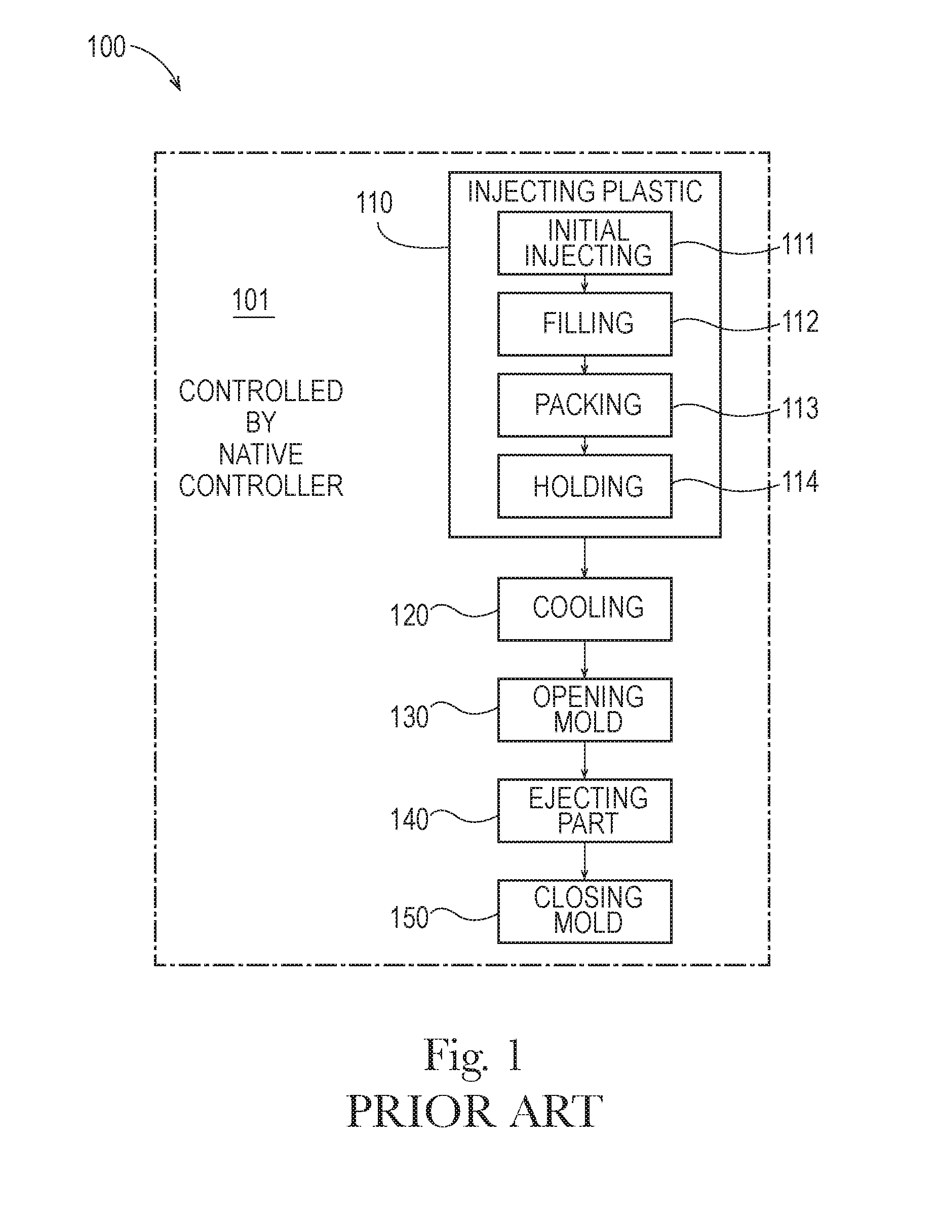
[0079]FIG. 1 is an illustration of an exemplary original injection mold cycle 100, as programmed on an exemplary native controller, such as the native controller 202 of FIGS. 2 and 3, for controlling 101 an injection molding machine, such as the exemplary injection molding machine 210 of FIG. 2, according to the prior art. The original injection mold cycle 100 includes an operating sequence of injecting molten plastic 110, cooling the plastic 120, opening the mold 130, ejecting the molded object from the mold 140, and closing the mold 150; these operations are often performed in this order, though there may be some overlap between certain operations, and in various embodiments, one or more additional operations may be added. The injecting of the molten plastic 110 includes an initial injecting portion 111, a filling portion 112, a packing portion 113, and a holding portion 114; however, in various embodiments, injecting may include different portions. The injecting of the molten pla...


PUM

PropertyMeasurementUnit
pressureaaaaaaaaaa
pressureaaaaaaaaaa
pressureaaaaaaaaaa

Abstract

An injection molding machine that uses a mold and a native controller to operate according to an original mold cycle to mold plastic objects is retrofitted with a retrofit controller; the retrofitted machine uses the mold and the retrofit controller to operate according to a retrofit mold cycle to mold plastic objects.

Description

FIELD OF THE INVENTION[0001]The present application generally relates to injection molding, and specifically relates to injection molding machines that are retrofitted with a controller having a retrofit mold cycle.BACKGROUND OF THE INVENTION[0002]Injection molding machines are commonly used to mold plastic objects. An injection molding machine molds plastic objects by repeatedly performing a mold cycle. During each mold cycle, the machine injects molten plastic into a mold, cools the plastic, opens the mold, ejects the molded object, closes the mold, and recovers for the next cycle. Various injection molding machines include variations of this mold cycle, as known in the art. A controller, which is programmed with the mold cycle, controls the machine according to the mold cycle.[0003]Injection molds are designed to mold particular objects from particular plastics at particular pressures. Injection molding machines are designed to accept a range of mold sizes and to inject plastic w...

Claims


Application Information

Patent Timeline
Patent Type & Authority Applications(United States)
IPC IPC(8): B29C45/77
CPCB29C45/77B29C45/76B29C2045/776B29C2945/76498B29C2945/76501B29C2945/76535B29C2945/76545B29C2945/76561B29C2945/76688B29C2945/76859B29C2945/76939B29C2945/76936B29C45/74B29C45/762B29C45/78B29C33/3842B29K2101/00
Inventor ALTONEN, GENE MICHAELDODD, MICHAEL THOMAS
Owner IMFLUX INC
Why Eureka
Try Eureka