Carriers for turbine components

a technology for gas turbine engines and carrier carriers, which is applied in the direction of machines/engines, stators, mechanical apparatus, etc., can solve the problems of difficult to meet the requirements of efficient cooling air delivery to the main radially inward cooling chamber, difficulty in providing a localised geometry or architecture that meets the conflicting requirements in an efficient manner, and difficulty in facilitating the provision. , the effect of simple shap

Active Publication Date: 2016-03-31
ROLLS ROYCE PLC
View PDF4 Cites 3 Cited by
  • Summary
  • Abstract
  • Description
  • Claims
  • Application Information

AI Technical Summary

Benefits of technology

[0030]It is a further advantage of the invention that the novel positioning of the conduits, channels or through-holes for providing improved access to the radially inward cooling chamber may also facilitate the provision therein of one or more sensors or other monitoring or control devices (e.g. in an experimental or test engine or even possibly in an in-use engine), which may require connection to external electrical control cabling. Thus, by providing an extra such conduit, channel or through-hole at a corresponding radial location to the others used to feed cooling air in to the chamber, or possibly by using one of the latter ones themselves, it is possible again to bypass the NGV-supporting flap plate rail or flange sealing arrangement which would otherwise make ready access to the interior of the cooling chamber from the outboard side of the engine, including for such a sensor and cabling arrangement, difficult.
[0031]In embodiments of the invention a wide variety of waveform shapes or functions may be used to define the undulating pattern in a circumferential direction at any particular longitudinal position traversing the carrier wall between its front and rear ends. For example, the undulating shape may be a waveform of any suitable mathematical function. The waveform is preferably a regular repeating wave having a constant or a regularly varying wavelength and/or amplitude.
[0032]By way of example, the wave function may define a relatively simple shape such as a part-cylindrical, part-polygonal, part-spherical, part-parabolic or part-hyperbolic curve. Alternatively, the wave function may define a more c...

Problems solved by technology

One of the challenges faced by engine designers is how to efficiently deliver a desired amount of cooling air, which is supplied from the HP compressor 20 having bypassed the combustor, to the required locations to the relevant components downstream of the combustor.
This is often difficult, taking into account the complex engine architecture and the fact that many of the components in question that need most cooling are associated with especially high temperatures and mechanical stresses when in operation, which makes the accommodation of differential expansion of such components and/or their carriers, shrouds, platforms, etc also a particularly challenging task.
With this known arrangement, however, the efficient delivery of cooling air to the main radially inward cooling chamber 70 presents practical difficulties.
The main issue is how to get sufficient flow rates of cooling air from the outboard feed source into the radially inward cooling chamber 70 effi...

Method used


Image

  • Carriers for turbine components
  • Carriers for turbine components
  • Carriers for turbine components

Examples


Embodiment Construction

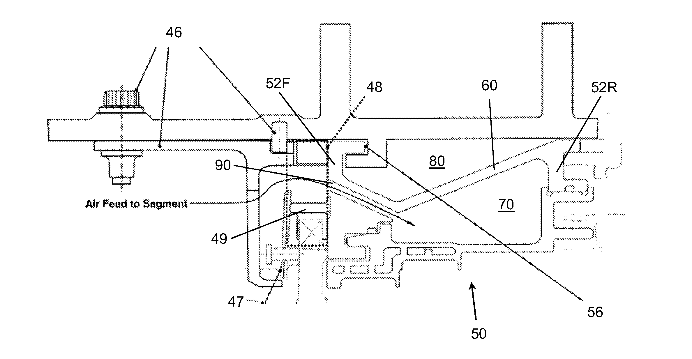
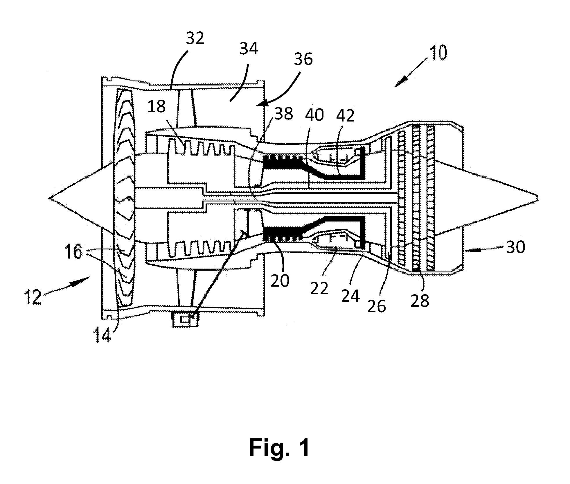
[0055]Referring firstly to FIG. 4 (FIGS. 1, 2, 3(a) and 3(b) having already been described in the context of the prior art), here there is shown a first embodiment of the invention, showing a single carrier segment 150 comprising front end wall or section 152F and rear end wall or section 152R. Extending longitudinally (relative to the engine axis) between the front and rear ends sections 152F, 152R is carrier wall 200F, 200R, which has an example of the characteristic new shape and / or configuration in accordance with this embodiment of the invention. The front end section 152R includes a flap plate rail or flange 149 for supporting and pinning to an NGV (not shown), which also forms part of the important sealing arrangement in this region of the engine for isolating the inboard hot section containing the NGVs, turbine blades, etc. from the outboard region containing the cooling air feed source.

[0056]The carrier wall 200F, 200R itself is of substantially uniform thickness, e.g. of a...


PUM


Abstract

A carrier segment for forming a carrier section for one or more gas turbine engine components, the carrier segment including a carrier wall extending between front and rear carrier ends and having a circumferential profile, the carrier segment being configured for defining radially inwardly thereof a chamber for receiving cooling air from an outboard feed source via the front end, wherein the circumferential profile of the carrier wall is undulating, e.g. with a simple waveform configuration or a more complex arrangement of interleaved series of oppositely oriented part-conical surface formations.

Description

TECHNICAL FIELD[0001]This invention relates to carriers for components of a gas turbine engine. More particularly, though not exclusively, the invention relates to improvements in the geometry of carriers, and segments for forming such carriers, for turbine components requiring especially high or efficient levels of cooling, such as nozzle guide vanes (NGVs), turbine blades, as well as other components.BACKGROUND OF THE INVENTION AND PRIOR ART[0002]FIG. 1 of the accompanying drawings is a schematic representation of a known aircraft ducted fan gas turbine engine 10 comprising, in axial flow series: an air intake 12, a propulsive fan 14 having a plurality of fan blades 16, an intermediate pressure compressor 18, a high-pressure compressor 20, a combustor 22, a high-pressure turbine 24, an intermediate pressure turbine 26, a low-pressure turbine 28 and a core exhaust nozzle 30. A nacelle 32 generally surrounds the engine 10 and defines the intake 12, a bypass duct 34 and a bypass exha...

Claims


Application Information

Patent Timeline
IPC IPC(8): F01D5/02F01D9/04
CPCF01D5/02F01D9/04F01D9/042F01D25/14F01D25/246F05D2240/11F05D2250/184F05D2250/611F05D2240/91Y02T50/60
Inventor WATKIN, MEIRION
Owner ROLLS ROYCE PLC
Why Eureka
Try Eureka