
Production method of producing fiber-reinforced resin molding

a technology of fiber reinforced resin and production method, which is applied in the direction of coatings, etc., can solve the problems of inferior quality molding with strength variations, and achieve the effect of narrowing the rang

Active Publication Date: 2016-03-31
TOYOTA JIDOSHA KK
View PDF0 Cites 4 Cited by
  • Summary
  • Abstract
  • Description
  • Claims
  • Application Information

AI Technical Summary

Benefits of technology

The invention is a method of producing fiber-reinforced resin moldings with consistent physical properties. The method involves kneading resin with reinforcing fibers and then placing it in a molding device. By using opened reinforcing fibers instead of a roving of fibers, the length of the fibers after cutting become more uniform. This results in a more uniform range of physical properties for the molded product. The method also includes using a vent to prevent the buildup of air bubbles caused by the resin. Overall, this method produces fiber-reinforced resin moldings with consistent physical properties.

Problems solved by technology

A fiber-reinforced resin molding made of a kneaded mixture containing reinforcing fibers having a wide length distribution has physical property variations, and thus becomes an inferior-quality molding having strength variations.

Method used


Image

  • Production method of producing fiber-reinforced resin molding
  • Production method of producing fiber-reinforced resin molding
  • Production method of producing fiber-reinforced resin molding

Examples


first embodiment

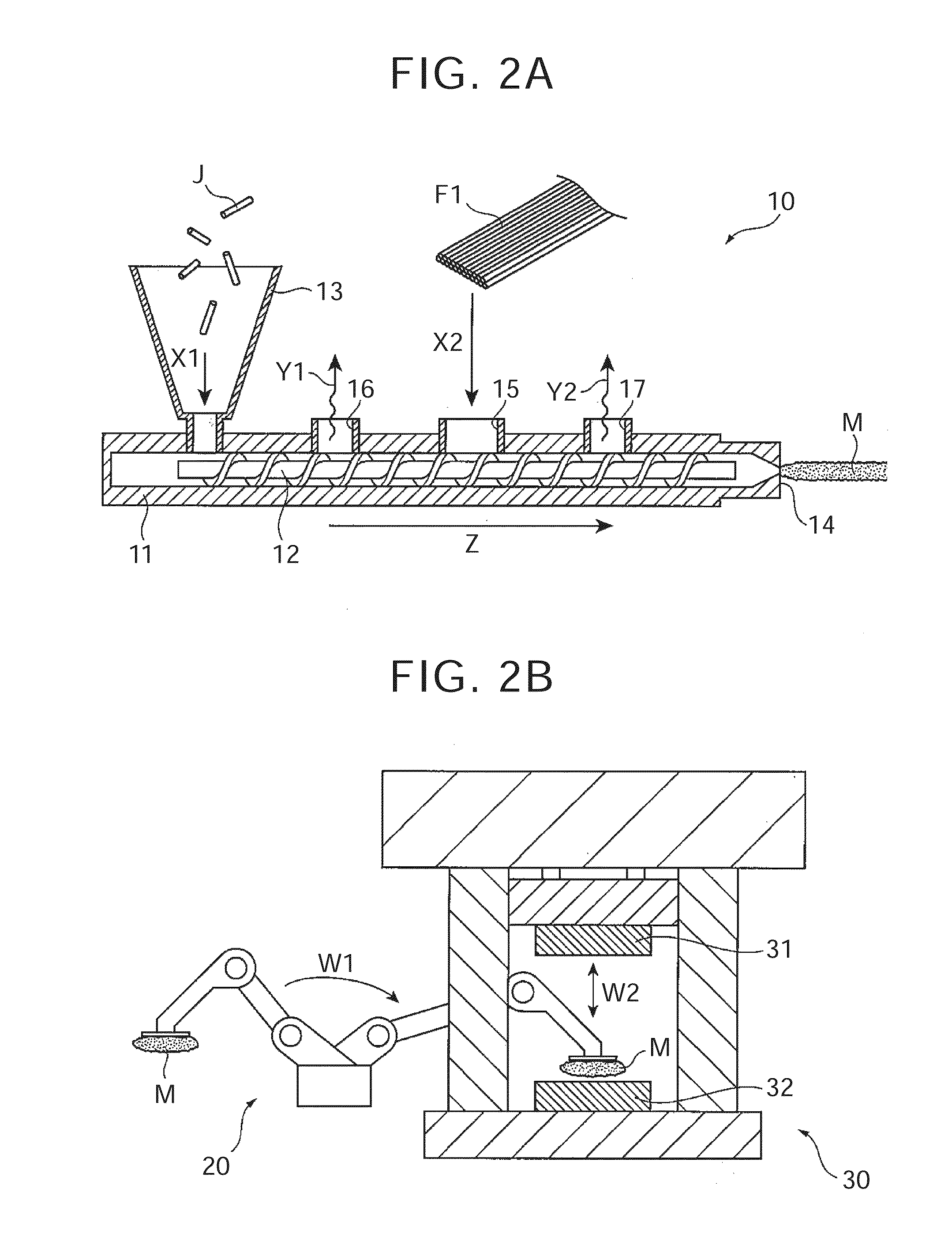
[0051]According to the production method in the first embodiment illustrated in FIG. 2A and FIG. 2B, the kneaded mixture M is produced by feeding the opened reinforcing fibers F1 into the kneader 10, and a fiber-reinforced resin molding is produced by placing the kneaded mixture M in the molding device 30. Thus, the external force (cutting force) applied from the kneader 10 to the opened reinforcing fibers F1 fed into the kneader 10 becomes as uniform as possible over the entire region of opened reinforcing fibers F1, so that the fiber lengths of the reinforcing fibers after cutting become as uniform as possible. As a result, the kneaded mixture M containing the reinforcing fibers having a narrower fiber length distribution is obtained. Therefore, it is possible to produce a high-quality fiber-reinforced resin molding with a narrower range of physical property variations.

[0052]Hereafter, the production method of producing a fiber-reinforced resin molding according to the second embo...

second embodiment

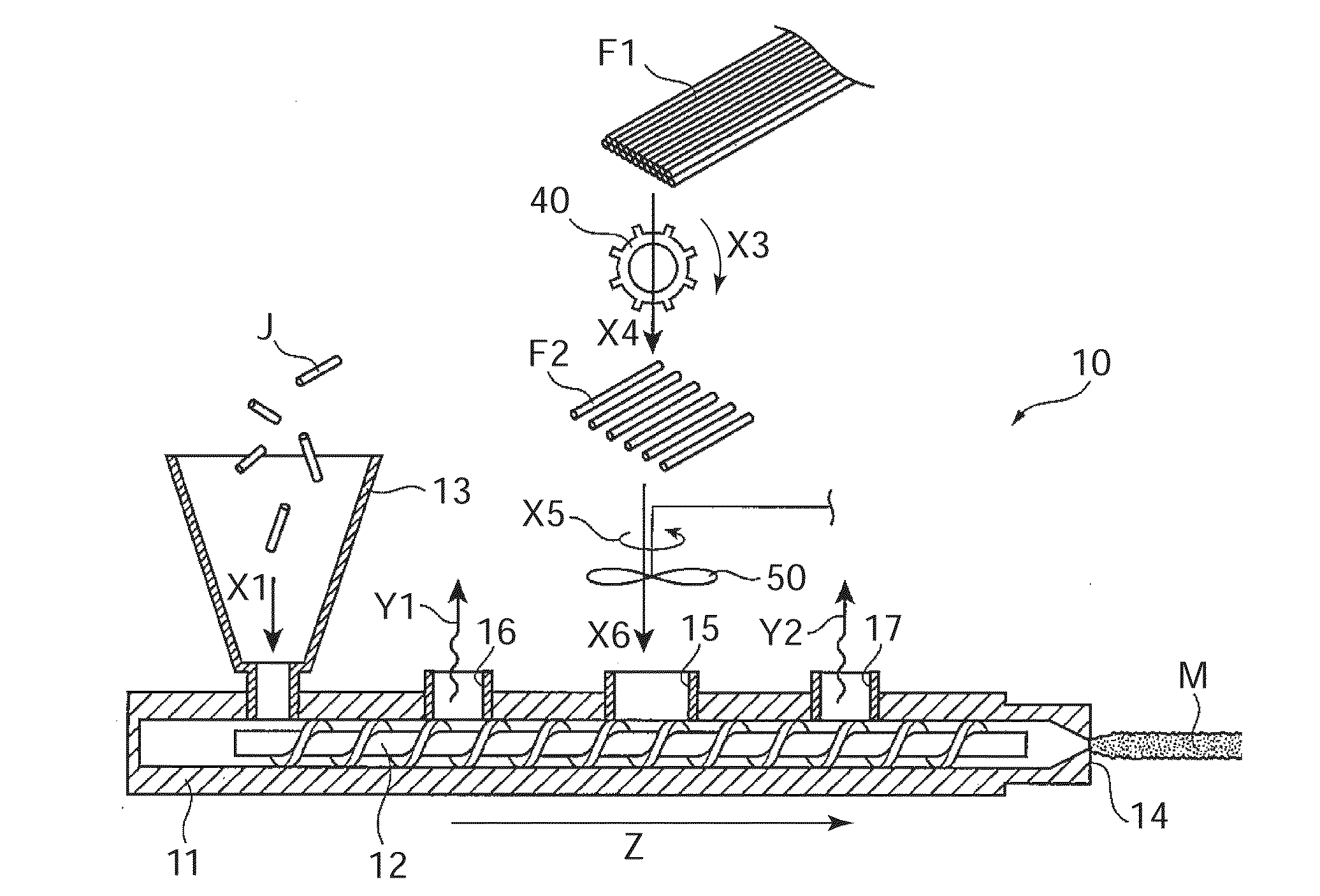
[0053]In the production method an airflow generator 50 is disposed above the fiber feed port 15 of the kneader 10. The airflow generator 50 is a fan, and serves as a feed assist mechanism that assists the introduction of the reinforcing fibers into the fiber feed port 15. Further, a cutter 40 is disposed above the airflow generator 50. The cutter 40 cuts the opened reinforcing fibers F1.

[0054]As the opened reinforcing fibers F1 pass along a direction X4 through the cutter 40 that is rotating along a direction X3, cut reinforcing fibers F2 having fiber lengths as uniform as possible are obtained. Then, the cut reinforcing fibers F2 thus obtained fall toward the fiber feed port 15.

[0055]The airflow generator 50, which is a fan, is disposed below the cutter 40, as the feed assist mechanism that assists the introduction of the cut reinforcing fibers F2 into the fiber feed port 15. Thus, the rotation of the airflow generator 50 along a direction X5 generates an airflow heading toward th...


PUM


Abstract

A production method of producing a fiber-reinforced resin molding includes: kneading, in a kneader, molten thermoplastic resin with opened reinforcing fibers obtained by opening a bundle of reinforcing fibers, to produce a kneaded mixture; and placing or charging the kneaded mixture into a molding device to produce a fiber-reinforced resin molding.

Description

INCORPORATION BY REFERENCE[0001]The disclosure of Japanese Patent Application No. 2014-195830 filed on Sep. 25, 2014 including the specification, drawings and abstract is incorporated herein by reference in its entirety.BACKGROUND OF THE INVENTION[0002]1. Field of the Invention[0003]The invention relates to a production method of producing a fiber-reinforced resin molding by kneading a resin with reinforcing fibers and then placing or charging a kneaded mixture into a molding device.[0004]2. Description of Related Art[0005]Being lightweight and highly strong, fiber-reinforced resin moldings (fiber-reinforced plastics (FRP)), which are made of resins mixed with reinforcing fibers, are used in various industrial fields, such as the automobile industry, the construction industry, and the aviation industry.[0006]For example, in the automobile industry, the fiber-reinforced resin moldings are applied to vehicular framework structural members, such as pillars, rockers, and lower floors, a...

Claims


Application Information

Patent Timeline
IPC IPC(8): B29C45/00B29C45/18B29C45/63B29C48/40B29C48/76
CPCB29C45/0005B29C45/0001B29C45/1816B29K2307/04B29K2105/12B29K2101/12B29C45/63B29C43/003B29C43/34B29C2043/3411B29K2267/00B29K2305/00B29K2309/02B29K2309/08B29K2277/00B29C48/022B29C48/288B29C48/297B29C48/767B29C48/2886B29B7/90B29B7/905B29B7/603B29B7/845B29C48/40B29B7/42
Inventor ODA, TETSUYA
Owner TOYOTA JIDOSHA KK
Learn More