
A frame assembly for an air filter

a frame assembly and air filter technology, applied in the direction of filtration separation, separation process, dispersed particle separation, etc., can solve the problems of global pandemic and devastation, and achieve the effect of reducing the risk of human error and improving the safety level of the air handling system

Active Publication Date: 2016-03-10
CAMFIL AB
View PDF0 Cites 5 Cited by
  • Summary
  • Abstract
  • Description
  • Claims
  • Application Information

AI Technical Summary

Benefits of technology

The present invention provides an improved frame assembly for an air handling system that eliminates or reduces the drawbacks of existing frames. The frame assembly reduces the risk of human error and provides better safety in air handling. The actuator of the mechanical clamping ensures that the filter unit is placed correctly in the frame and bears against the back member of the frame before the clamping mechanism can be activated. The front member has an opening for the actuator element. The clamping mechanism is a spring loaded clamping device that quickly clamps the filter unit air tight towards the receiving face of the filter housing. The air handling assembly also includes a door for sealing an access opening of the compartment with a blocking element preventing the door from closing if the actuator of the clamping mechanism is not in a closed position.

Problems solved by technology

A potential problem with clamping mechanism of the above type and others is that any mistake made during replacement of the filters in the air handling system, e.g. if the filters are not properly positioned, the clamping mechanism are not properly closed etc, could have devastating effects like causing a global pandemic.

Method used


Image

  • A frame assembly for an air filter
  • A frame assembly for an air filter
  • A frame assembly for an air filter

Examples


Embodiment Construction

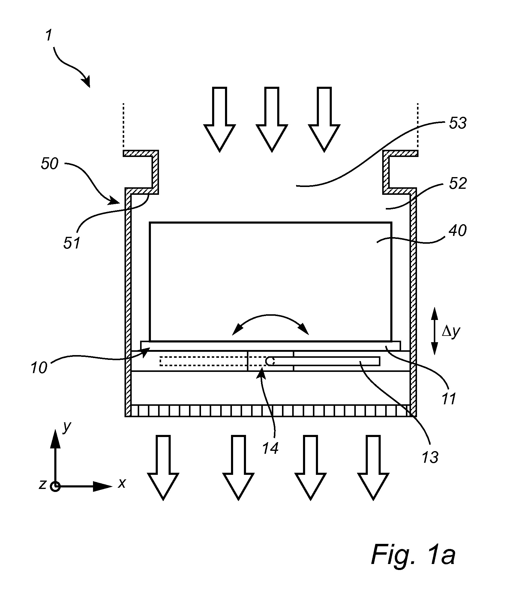
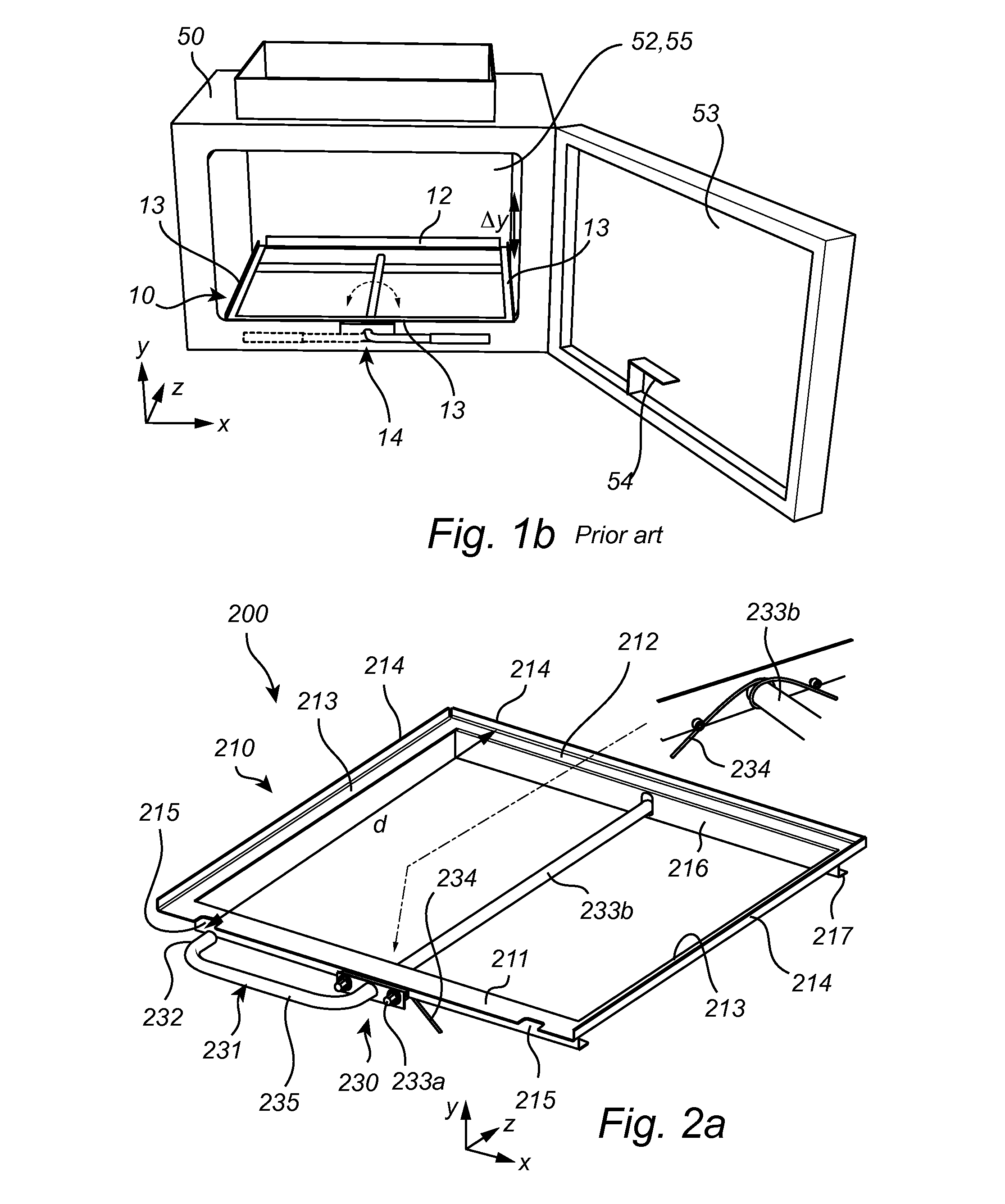
[0020]FIG. 1a is a cross-sectional view of a portion of an air handling assembly 1 schematically illustrating a filter housing 50 in which a replaceable filter unit 40 is arranged. The filter housing 50 is here a gastight, welded sheet steel construction having a compartment 52 in which a frame assembly 10 is disposed. The housing 50 may include an access opening and a corresponding door for facilitating maintenance, installation of, or removal of the filter unit 40, see FIG. 1b. The frame assembly 10 is movably coupled to the housing and is arranged to receive and support the filter unit 40 when in position. The frame assembly 10 includes an aperture that is adapted to allow air to pass there through, and is adapted to move in the y-direction to push the filter unit 40 against a holding frame defined by surface 51 of the compartment 52. The movement in the y-direction of the frame assembly 10 is governed by a clamping mechanism 14. The clamping mechanism 14 is arranged to clamp the...


PUM

PropertyMeasurementUnit
sizeaaaaaaaaaa
trajectoryaaaaaaaaaa
distanceaaaaaaaaaa

Abstract

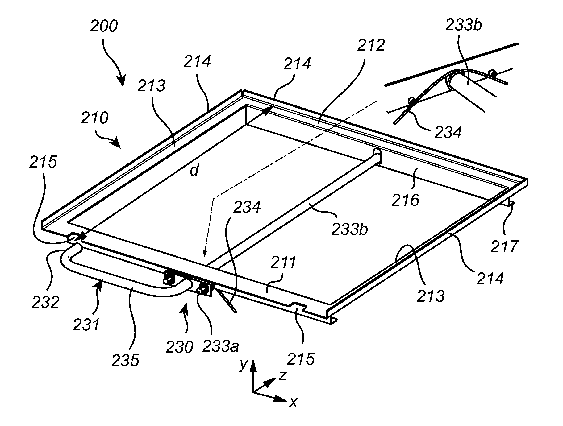
There is provided a frame assembly 200 adapted for installation in a filter housing of an air handling system. The frame assembly is arranged having a frame 210 which is adapted to receive a filter unit of a predetermined size. The frame assembly further comprises a clamping mechanism 230 arrange for clamping the filter unit. An actuator 231 of the clamping mechanism is arranged at a front member 211 of the frame and is operable between an open and a closed position while activating the clamping mechanism to clamp the filter unit. An actuator element 232 facing a back member 212 of the frame is arranged such that a free distance between the actuator element and the back member during operation of the actuator corresponds to the predetermined filter unit size, thereby enabling operation of the actuator only if an inserted filter unit abuts the back member of the frame.

Description

FIELD OF THE INVENTION[0001]The present invention relates to air handling systems and more particularly to a frame assembly adapted for clamping an air filter unit in a filter housing.BACKGROUND OF THE INVENTION[0002]In air filtration systems requiring high efficiency filters such as High-Efficiency Particulate Air (HEPA) filters and other high efficiency filters, it is known to use some type of filter holding frame and a mechanical clamping mechanism to secure and effectively seal the filter to the holding frame. Such holding frames may be positioned within air ducts or filter housings of the air handling system. WO2012 / 134650 discloses a filter holding frame with an adjustable mechanical clamping mechanism including a frame having a downstream member coupled to a cross member, the downstream member and the cross member being adapted to fit within a housing. The frame assembly comprises at least two clamping mechanisms each coupled to a respective handle which is used to displace t...

Claims


Application Information

Patent Timeline
Patent Type & Authority Applications(United States)
IPC IPC(8): B01D46/10B01D46/00
CPCB01D46/10B01D46/0005B01D2265/026B01D2265/028B01D2273/14
Inventor NATIONAL, PASCAL
Owner CAMFIL AB
Learn More