
Multi-sensor pedometer

a multi-sensor, pedometer technology, applied in the field of pedometers, can solve the problems of giving a false reading, pedometers getting dramatically affected, false measurements of what their activity is,

Inactive Publication Date: 2016-01-28
BHATTACHARYYA AMITABHA
View PDF6 Cites 10 Cited by
  • Summary
  • Abstract
  • Description
  • Claims
  • Application Information

AI Technical Summary

Benefits of technology

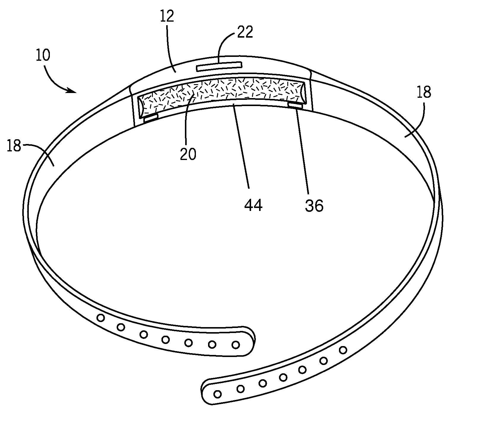
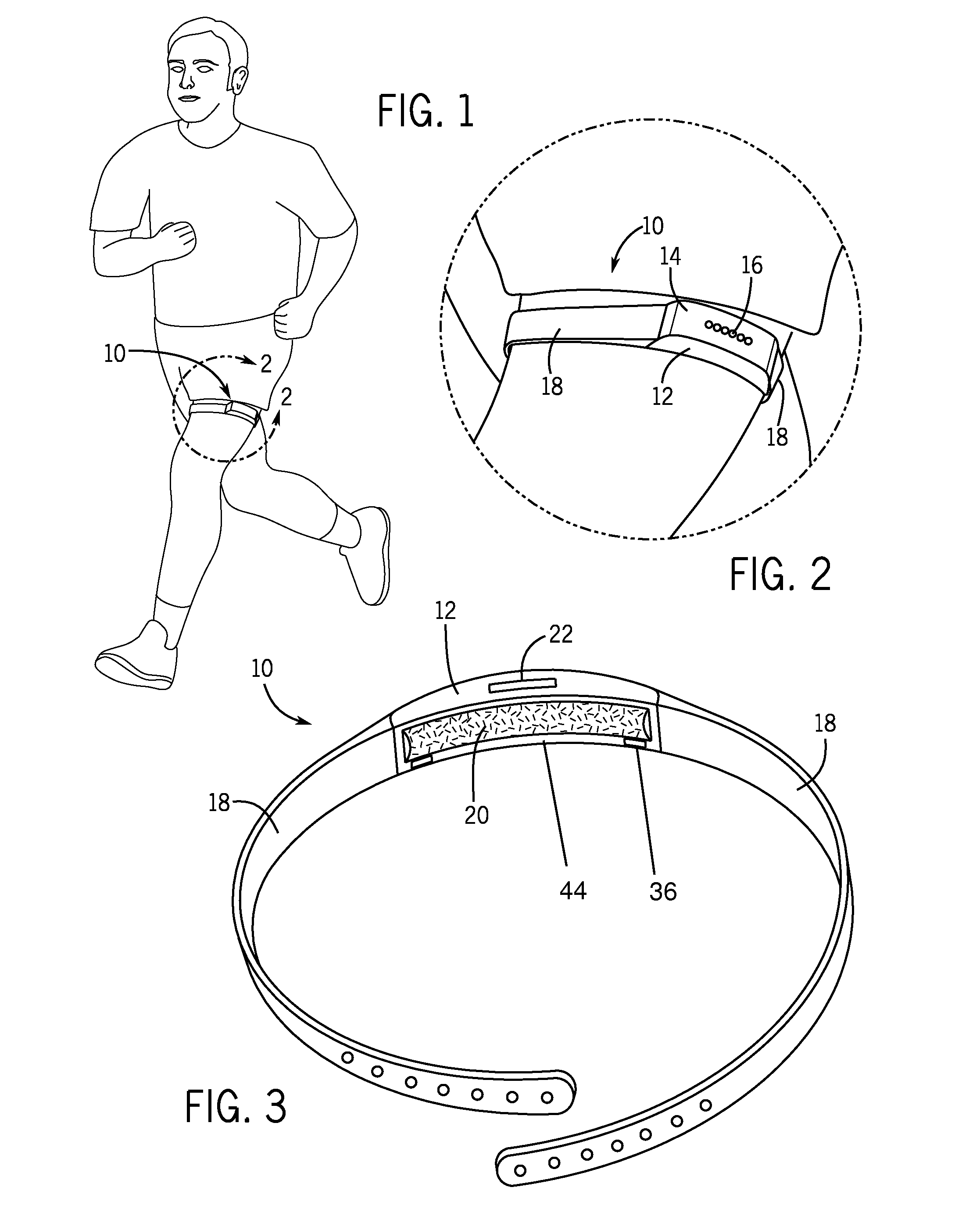
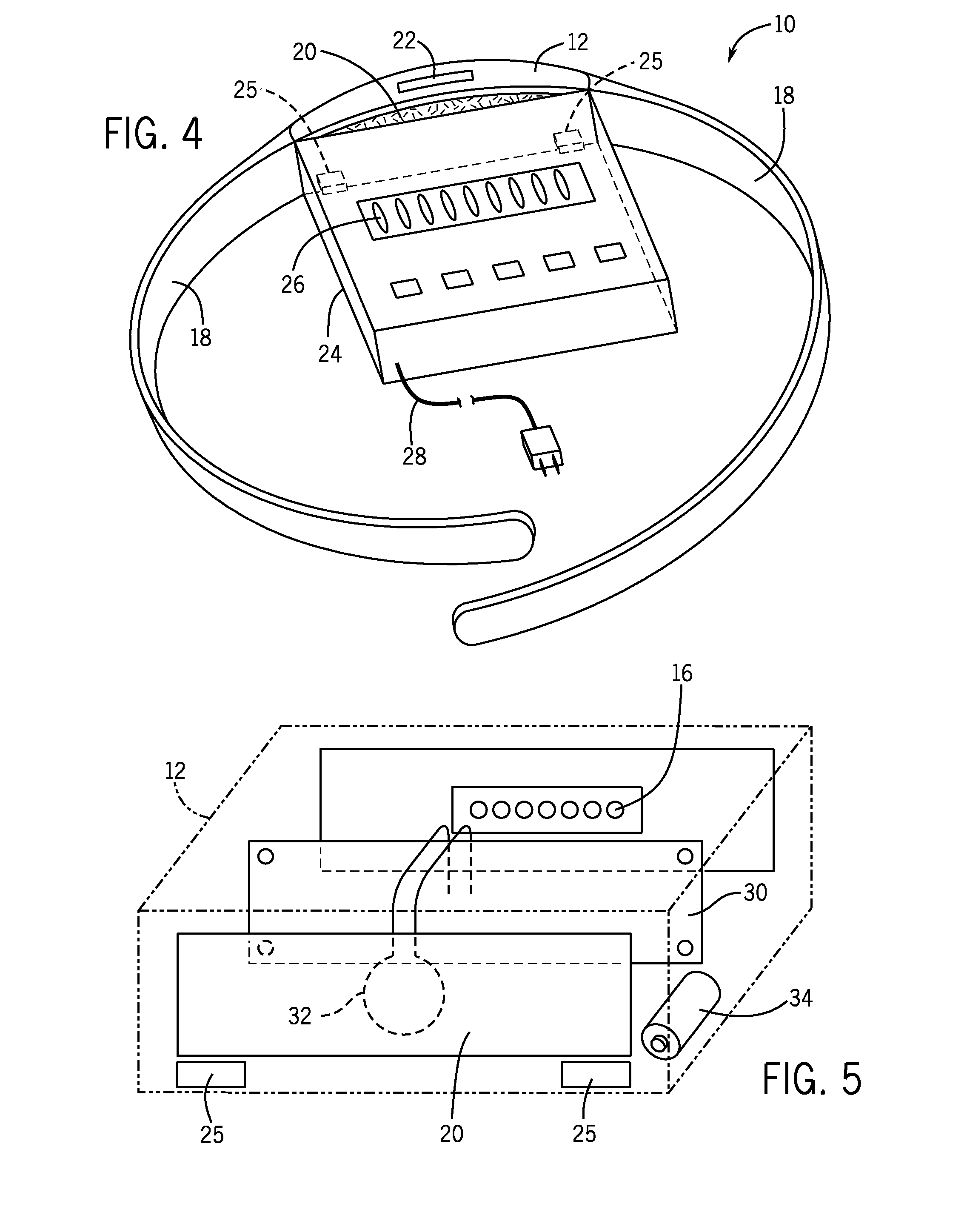
The present invention is a multi-sensor pedometer that includes a sensing film, piezo-electric sensor, accelerometer, and control circuitry. The sensing film produces a predictable flexing when interacting with a specific muscle, and the piezo-electric sensor sends an electronic step signal for every flexing. The accelerometer detects proper acceleration and sends a motion signal. The control circuitry counts the identifiable step when the motion signal is received. Additionally, the invention includes a counting system comprising a counting gate and a step counter. The counting gate moves from a closed position to an open position after receiving the electronic step signal and counts the step when the gate is in the open position. The invention enables accurate tracking of steps during physical activity.

Problems solved by technology

As a result, movement (or lack thereof) on any of these parts of the body for any other reason than walking or running may give a false reading.
Moreover, pedometers get affected dramatically when jostled or otherwise shifted from their optimal placements during exercise.
Considering that pedometers are used to maintaining healthy physical activity, errors can give users false measurements of what their activity is and so give false health-related information when the user is arranging their exercise regime within their lifestyle.

Method used


Image

  • Multi-sensor pedometer
  • Multi-sensor pedometer
  • Multi-sensor pedometer

Examples


Embodiment Construction

[0012]The following detailed description is of the best currently contemplated modes of carrying out exemplary embodiments of the invention. The description is not to be taken in a limiting sense, but is made merely for the purpose of illustrating the general principles of the invention, since the scope of the invention is best defined by the appended claims.

[0013]Broadly, an embodiment of the present invention provides a multi-sensor pedometer. The multi-sensor pedometer may include a first housing having a plurality of sidewalls forming an encased compartment. The plurality of sidewalls may provide at least one strap, a display and a sensing film. The compartment may house a control circuitry, a piezo-electric sensor and a power source. The control circuitry may provide an accelerometer and a step counting system including a step counter. A user may secure the multi-sensor pedometer around at least a portion of a predetermined muscle used during their exercise by connecting the at...


PUM


Abstract

A multi-sensor pedometer is provided. The multi-sensor pedometer may include a first housing having a plurality of sidewalls forming an encased compartment. The plurality of sidewalls may provide at least one strap, a display and a sensing film. The compartment may house a control circuitry, a piezo-electric sensor and a power source. The control circuitry may provide an accelerometer and a step counting system including a step counter. A user may secure the multi-sensor pedometer around at least a portion of a predetermined muscle used during their exercise by connecting the at least one strap so that the sensing film operably interfaces the predetermined muscle. When the user prepares to exercise, the muscle contraction / bulge is conveyed through the sensing film to the electromechanically connected piezo-electric sensor, resulting in the step signal being sent to the control circuitry. The accelerometer transmits a motion signal to the control circuitry when it is detecting proper motion. The counting system counts at least one identifiable step when receiving the motion signal within a predetermined time of receiving any step signal. The control circuitry may electronically represent the summation of the at least one identifiable step and an associated plurality of exercise data on the display.

Description

BACKGROUND OF THE INVENTION[0001]The present invention relates to a method, device and system for accurately measuring exercise performance and, more particularly, to a pedometer that accurately counts the steps of a user by two independent sensors of motion and muscle contraction.[0002]A pedometer is a device that usually counts each step a person takes by detecting the motion of the person's hips. The accuracy of step counters varies widely between devices. Typically, step counters are placed on a belt, an arm or a wrist or otherwise far from the legs that take the steps to be counted. As a result, movement (or lack thereof) on any of these parts of the body for any other reason than walking or running may give a false reading. In other words, traditional pedometers give falsely counted steps when a user is driving a car or makes other habitual motions that the device encounters throughout the day. Moreover, pedometers get affected dramatically when jostled or otherwise shifted fr...

Claims


Application Information

Patent Timeline
Patent Type & Authority Applications(United States)
IPC IPC(8): G01C22/00
CPCG01C22/006
Inventor BHATTACHARYYA, AMITABHA
Owner BHATTACHARYYA AMITABHA
Learn More