
Low-collateral damage directed fragmentation munition

a technology of low-collateral damage and fragmentation, applied in the direction of ammunition projectiles, weapons, projectiles, etc., can solve the problems of fracture of steel casing into metal fragments, tight timing tolerances for aimpoint and detonation, and high cos

Active Publication Date: 2016-01-28
RAYTHEON CO
View PDF0 Cites 10 Cited by
  • Summary
  • Abstract
  • Description
  • Claims
  • Application Information

AI Technical Summary

Benefits of technology

The solution enhances the safety and effectiveness of the munition by ensuring fragments are expelled with sufficient force while minimizing collateral damage, with the casing and ring disintegrating into harmless particles, reducing the lethality radius and protecting friendly troops.

Problems solved by technology

In other words, the mass efficiency is the ratio of the total mass less the interstitial mass that was consumed during the launch process (therefore ineffective against the intended target) to the total mass.
As a result, the warhead has a maximum lethality confined to a very narrow angle and expels a certain amount of lethal fragments outside the desired target area that may cause collateral damage.
This means that the aimpoint and detonation timing tolerances to engage and destroy the threat while minimizing collateral damage are tight.
The detonation and subsequent expansion also fractures the steel case into metal fragments of various shapes and sizes that are thrown in all directions, beyond the lethality radius of the blast.
Fragmentation of the steel case increases the potential for collateral damage without improving the lethality of the warhead to destroy the threat.
However this approach does not fully address the problems of producing a desired spread of fragments while reducing potential collateral damage from the munition.

Method used


Image

  • Low-collateral damage directed fragmentation munition
  • Low-collateral damage directed fragmentation munition
  • Low-collateral damage directed fragmentation munition

Examples


Embodiment Construction

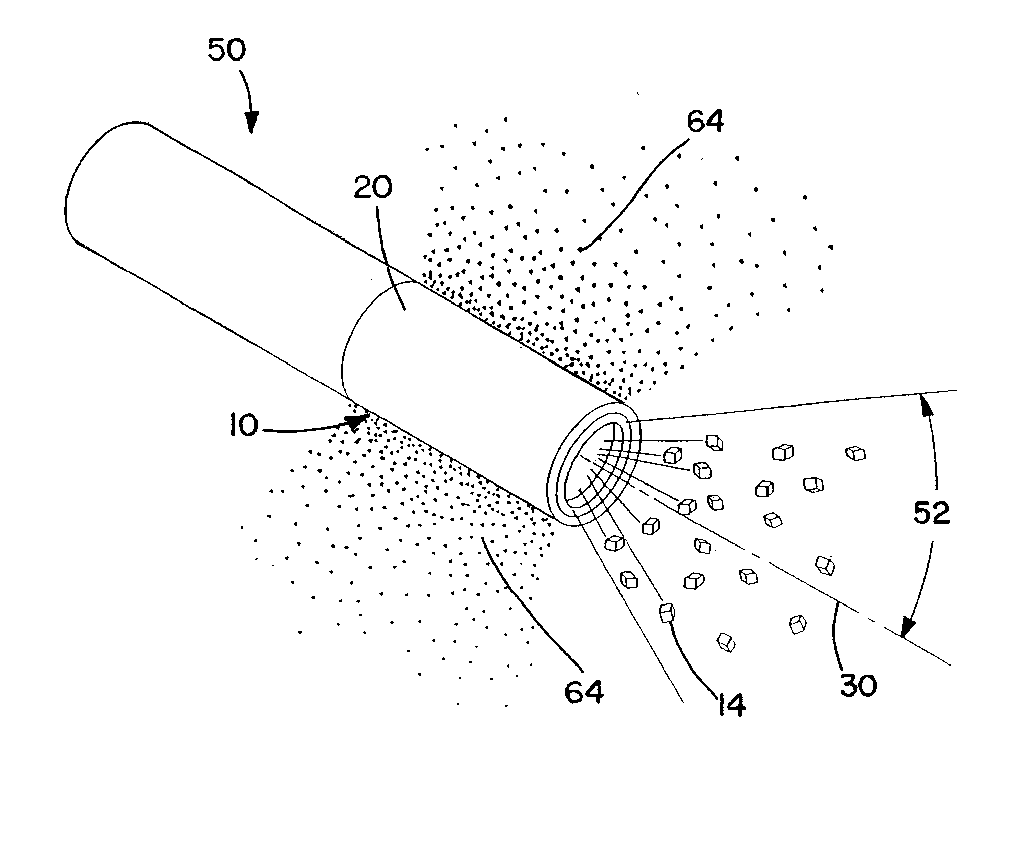
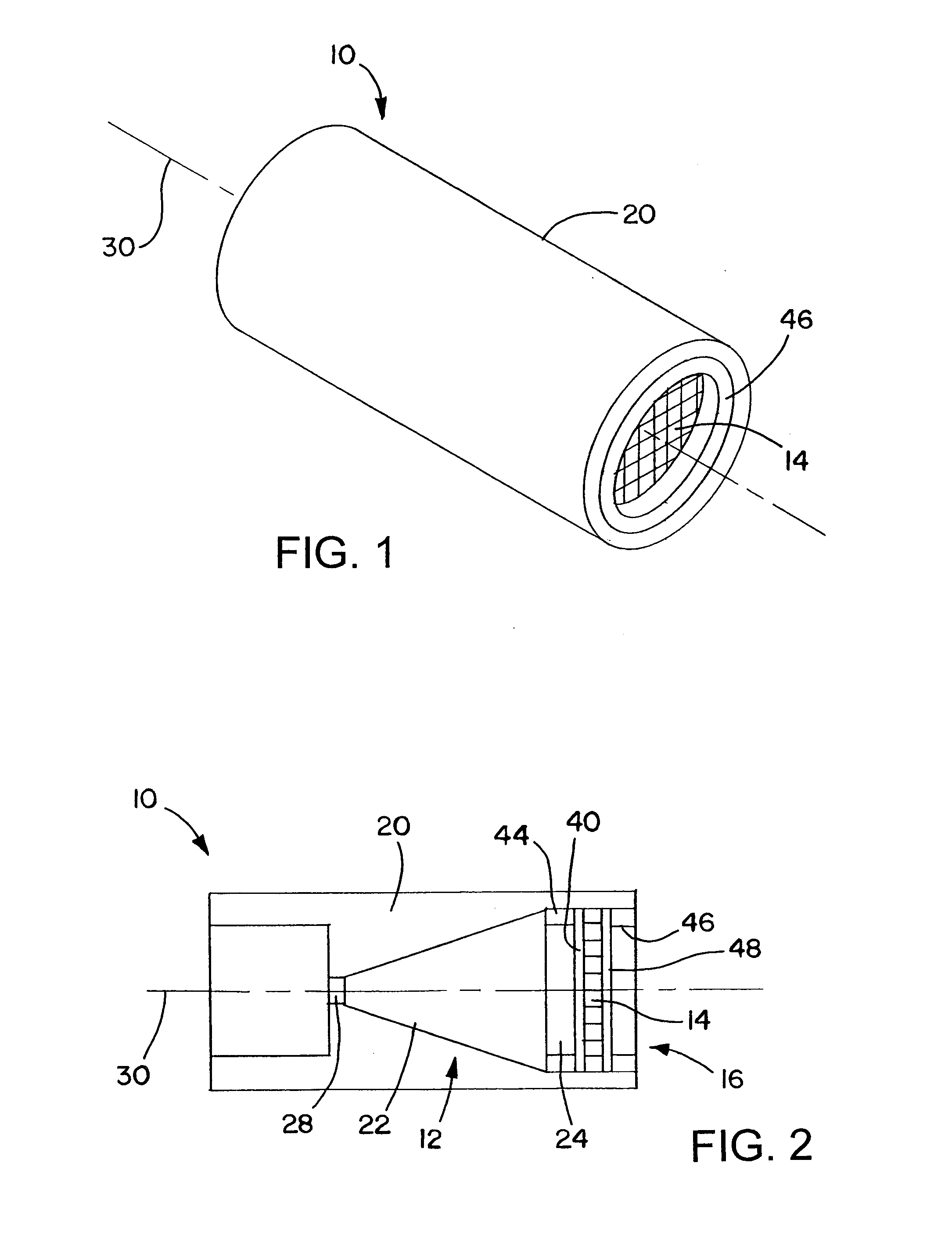
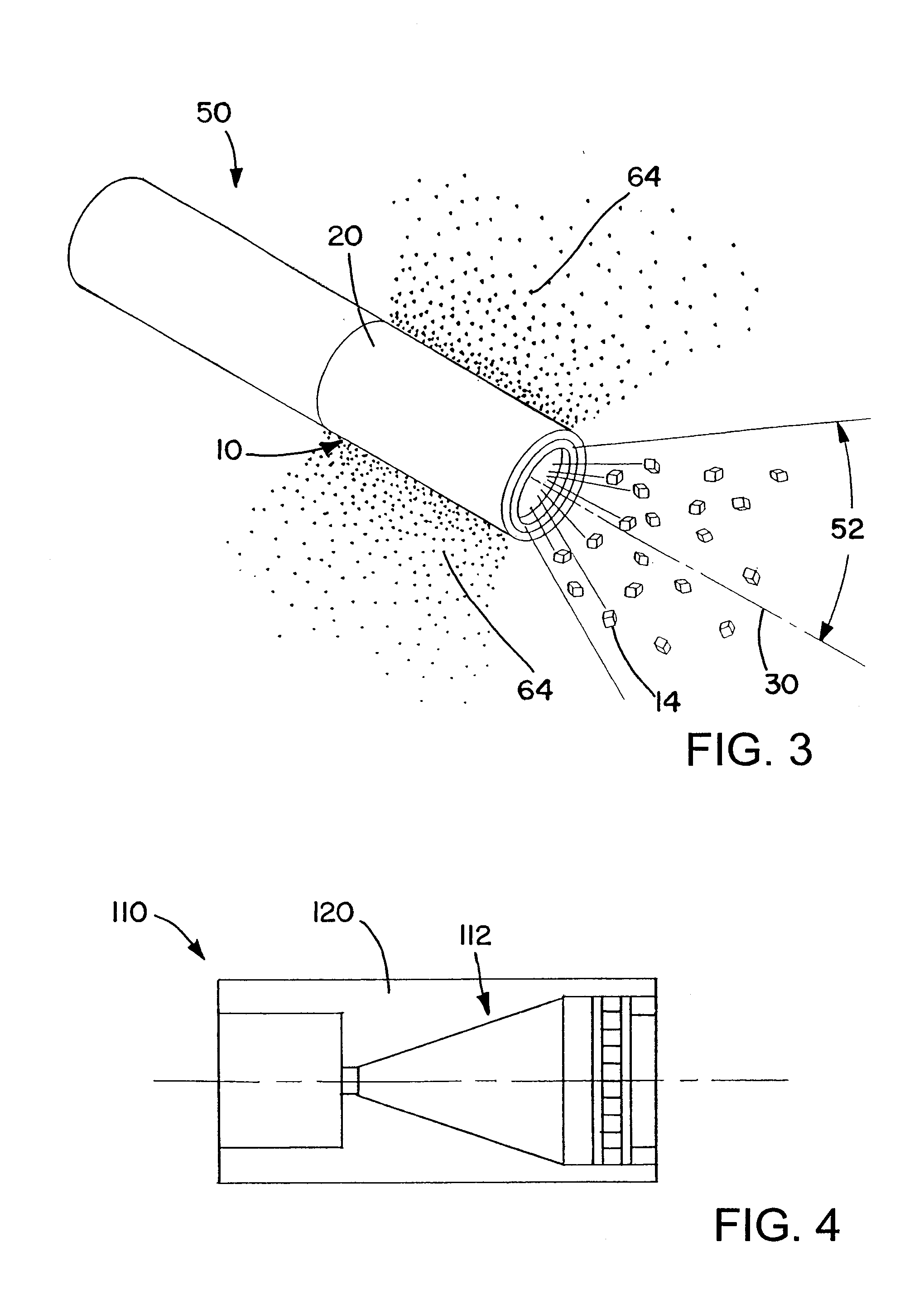
[0014]A directed munition has a non-fragmentation casing, and an explosive within the casing that is configured to propel fragments out an opening of the casing when the explosive is detonated. The casing may be made of plastic or a composite material, or another low density material that does not produce lethal or injurious fragments when the explosive is detonated. The explosive may include an insensitive explosive portion that creates the shape of an explosive front, and a secondary explosive containing a more energetic explosive, which is closer to the fragments than the insensitive explosive portion. There may be more of the insensitive explosive than the relatively energetic explosive, with the insensitive explosive for example constituting a majority of the circumferential surface area of the explosive.

[0015]FIGS. 1 and 2 show a munition 10 that uses an explosive 12 to direct fragments 14 out of an opening 16 in the front of a casing 20 that encloses the explosive 12 and the ...


PUM


Abstract

A directed munition has a non-fragmentation casing, and an explosive within the casing that is configured to propel fragments out an opening of the casing when the explosive is detonated. The casing may be made of a material that does not produce lethal or injurious fragments when the explosive is detonated. The explosive may include an insensitive explosive portion that creates the shape of an explosive front, and a secondary explosive containing a more energetic explosive, which is closer to the fragments than the insensitive explosive portion. There may be more of the insensitive explosive than the relatively energetic explosive. The munition may have a ring that is operatively coupled to the fragments, to aid in directing the fragments out of the casing opening in a desired direction. The ring may be made of a material that does not produce injurious fragments when the explosive is detonated.

Description

FIELD OF THE INVENTION[0001]The invention relates to fragmentation munitions and warheads.DESCRIPTION OF THE RELATED ART[0002]Fragmentation warheads expel metal fragments upon detonation of an explosive. Fragmentation warheads are used as offensive weapons or as countermeasures to anti-personnel or anti-property weapons such as rocket-propelled grenades. A typical warhead includes an explosive inside a steel case. A booster explosive and safe and arm device are positioned in an aft section of the case to detonate the main explosive. A fragmentation assembly is placed in an opening in a fore section of the case against the flat leading surface of the explosive. The fragmentation assembly will typically include scored metal or individual fragments (pre-formed) such as spheres or cubes to control the size and shape of the fragments so that the fragments are expelled in a predictable pattern and speed. Scored metal produces about an 80% mass efficiency while individual fragments are exp...

Claims


Application Information

Patent Timeline
Patent Type & Authority Applications(United States)
IPC IPC(8): F42B12/22
CPCF42B12/22F42B12/205F42B12/207F42B12/208F42B12/32
Inventor BOTTHOF, BRIAN S.CHRISTIANSON, KIM L.KIM, HENRI Y.HALL, GARRETT L.
Owner RAYTHEON CO
Learn More