
Flexible electronic device housing

a flexible, electronic device technology, applied in the direction of electric apparatus casings/cabinets/drawers, instruments, portable computers, etc., can solve the problems of limited pivoting angle and device can only be bent in one direction, and achieve the effect of avoiding stretching, compressing, or even breaking an electronic device, and convenient and safe ways to transport and store relatively large flexible electronic devices

Inactive Publication Date: 2016-01-14
STROETMANN CHRISTIAN
View PDF34 Cites 37 Cited by
  • Summary
  • Abstract
  • Description
  • Claims
  • Application Information

AI Technical Summary

Benefits of technology

The invention is a flexible housing for electronic devices that features a hinge-based joint means. The housing can fold even with a large curvature radius without putting pressure and stress on the electronic device. The flexible housing prevents the device from being bent below a certain radius, which is particularly useful for flexible display devices. This avoids stretching, compressing, or even breaking the device while still allowing for easy and safe transport and storage. Additionally, the flexible housing can provide an adjustment means.

Problems solved by technology

Furthermore, the device can only be bent in one direction starting from the completely flat out configuration and only with a very limited pivoting angle.

Method used


Image

  • Flexible electronic device housing
  • Flexible electronic device housing
  • Flexible electronic device housing

Examples


first embodiment

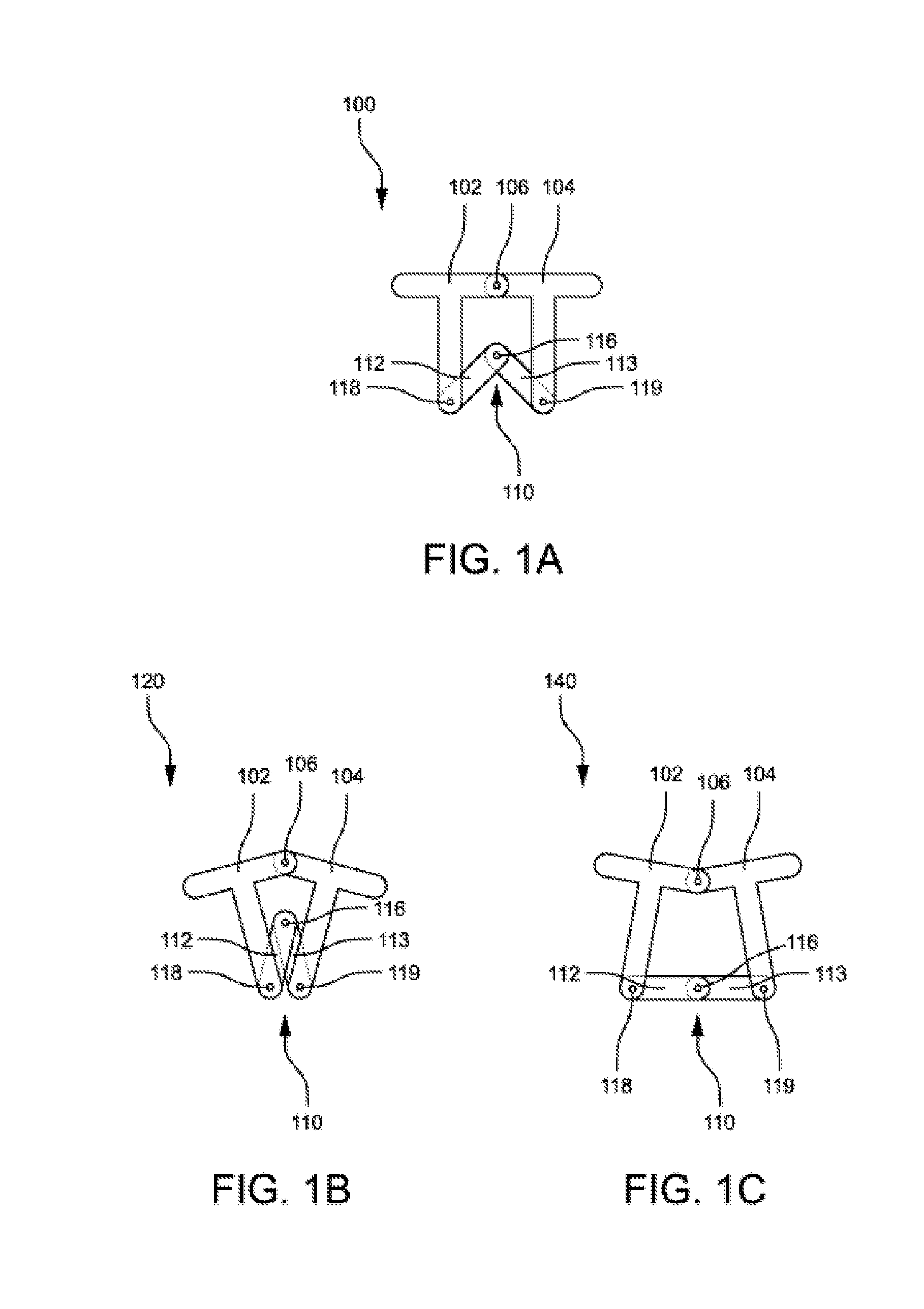
[0032]FIGS. 1A, 1B, and 1C illustrate an example of a basic joint means of a flexible device housing according to a The joint means comprises a first supporting element 102 and a second supporting element 104, which are shaped as T-pieces, and a third element 110. The third element 110 comprises a first member 112 and a second member 113, and is a hinge that is foldable respectively pivotable around the pivot 116. The supporting elements 102, 104 are a hinged means at their first sides, that is pivotable around the pivot 106, and are connected at their second sides by the third element 110, that is pivotable around the pivots 118, 119.

[0033]FIG. 1A shows the joint means with the third element in a flat out configuration 100, FIG. 1B shows the joint means with the third element in a folded configuration 120, and FIG. 1C shows the joint means with the third element in a bent configuration 140. As it can be seen in this example, the curvature radii of the folding and bending direction...

second embodiment

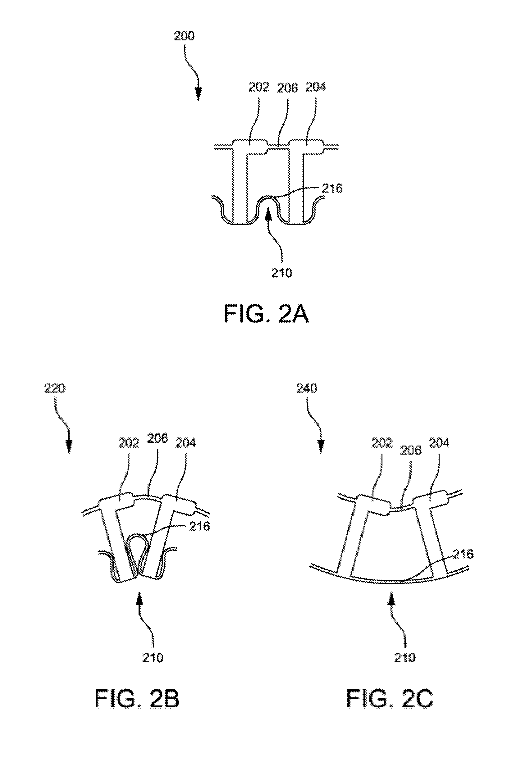
[0034]FIGS. 2A, 2B, and 2C illustrate an example of a basic joint means of a flexible device housing according to a The joint means comprises a first supporting element 202 and a second supporting element 204, which are shaped as L-pieces, and a third element 210. The third element 210 is a film hinge or living hinge 216. The supporting elements 202, 204 are a film hinge or living hinge at their first sides, that is bendable or pivotable around the section 206, and are connected at their second sides by the third element 210 respectively the film hinge 216.

[0035]FIG. 2A shows the joint means with the third element in a flat out configuration 200, FIG. 2B shows the joint means with the third element in a folded configuration 220, and FIG. 2C shows the joint means with the third element in a bent configuration 240. As it can be seen in this example as well, the curvature radii of the folding and bending directions depend on the dimensions and shape of the supporting elements 202, 204...

third embodiment

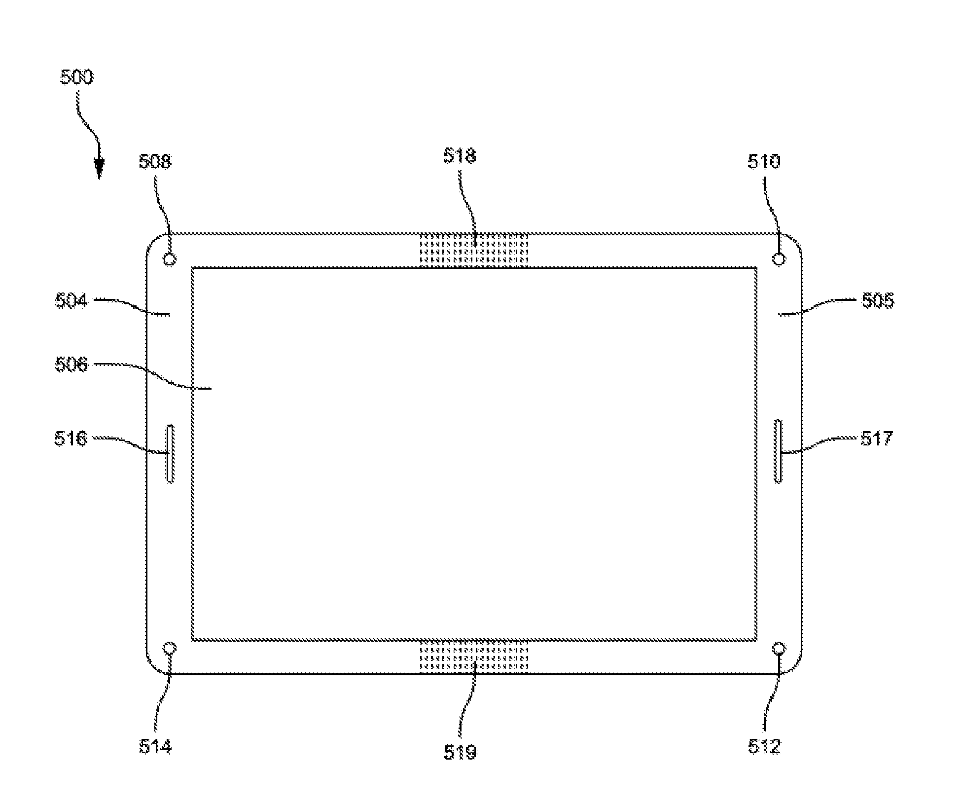
[0036]In order to provide various functionality described herein, FIGS. 3A and 3B illustrate an example of a flexible device housing according to a The flexible device housing comprises a first housing segment 304 and a second housing segment 305, which are connected by a foldable joint means 310. FIG. 3A shows the joint means with the third element in a folded configuration and FIG. 3B shows the joint means with the third element in a bent configuration.


PUM


Abstract

A flexible housing for electronic devices mounted on or contained within the housing is disclosed that features a relatively simple but nonetheless elaborated and functional foldable means or joint means. Depending on the special way of construction, dimensions, and features of the joint means elements the flexible housing permits the folding of the housing even with a large curvature radius without putting pressure and stress on a flexible respectively bendable electronic device mounted on or contained within the housing, such as a flexible display device and a flexible computing device for example. Moreover, the flexible housing prevents to go below the maximum permissible curvature radius of an installed flexible respectively bendable electronic device. Therefore on the one hand stretching, compressing or even breaking an electronic device is avoided and on the other hand easier and safer ways to transport and store relatively large flexible electronic devices are given. In some embodiments the flexible housing also provides an adjustment means.

Description

CROSS-REFERENCE TO RELATED APPLICATION[0001]This application claims the benefit of the German Utility Model Application No. 20-2014-103-159.6, filed Jul. 9, 2014, and entitled “Gerätegehäuse, das eine Befestigungsmöglichkeit für eine flexible beziehungsweise biegbare Anzeige and mindestens zwei Gehäuseteile hat, die durch ein Gelenk / Scharnier verbunden sind”, which is hereby incorporated by reference in its entirety.BACKGROUND[0002]1. Field of the Dislosure[0003]The present application relates generally to flexible housings of electronic devices. More particularly, the present invention pertains to flexible housings or cases comprising at least two segments, which are connected to each other by a joint or hinge means, a means for mounting a flexible display device, and an adjustment means to ease the usage, transportation, and storage of flexible electronic devices.[0004]2. Description of the Related Art[0005]In some disclosures electronic devices are described that have a flexible ...

Claims


Application Information

Patent Timeline
IPC IPC(8): H05K5/00H05K5/02
CPCH05K5/0217H05K5/0021G06F1/1616G06F1/1652G06F1/1675G06F1/1681
Inventor STROETMANN, CHRISTIAN
Owner STROETMANN CHRISTIAN
Learn More