Communication system
a communication system and communication technology, applied in the field of communication systems, can solve problems such as collision risks in rach, and achieve the effect of simple operation and administration, and easy operation and administration
- Summary
- Abstract
- Description
- Claims
- Application Information
AI Technical Summary
Benefits of technology
Problems solved by technology
Method used
Image
Examples
first embodiment
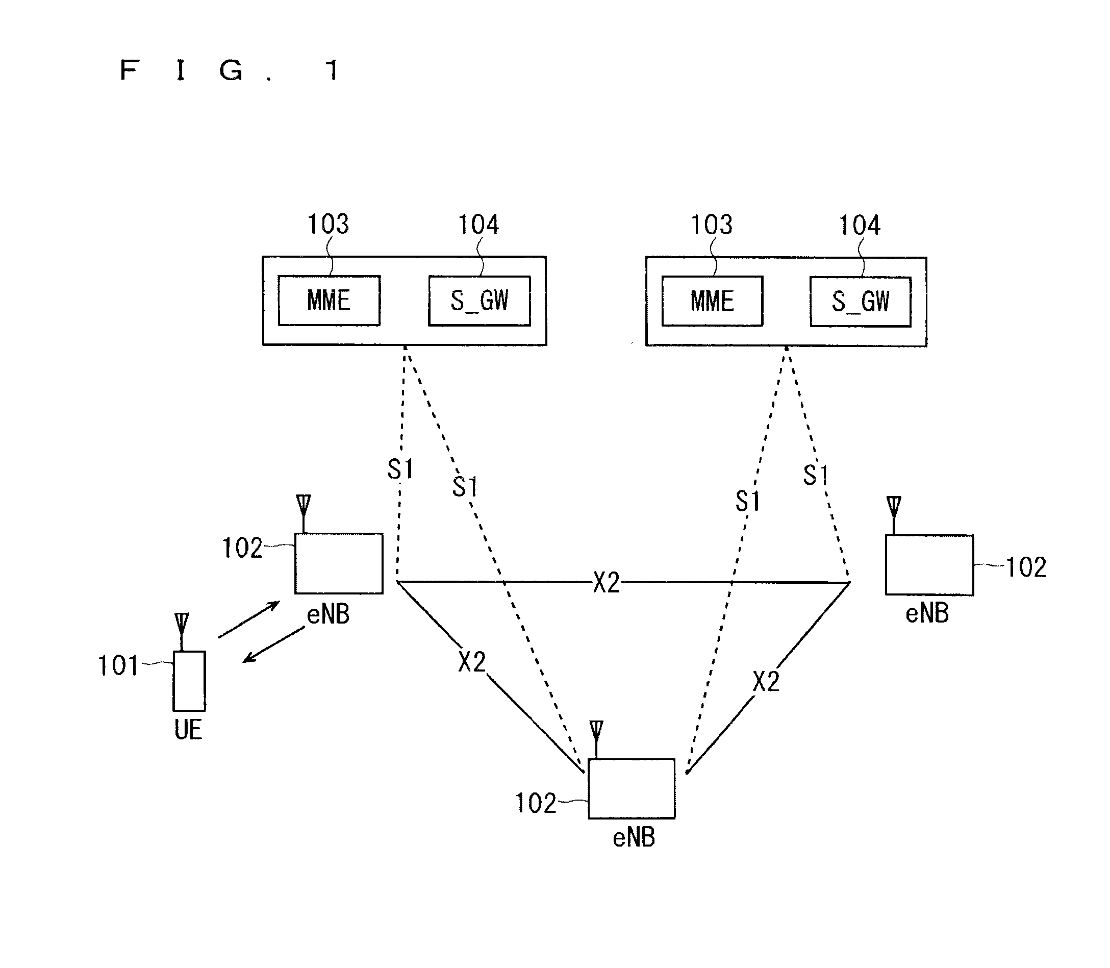
[0130]FIG. 7 is a block diagram showing an overall configuration of an LTE communication system, which is currently under discussion of 3GPP. 3GPP has studied an overall configuration of a system including closed subscriber group (CSG) cells (Home-eNodeBs (Home-eNB; HeNB) of E-UTRAN, Home-NB (HNB) of UTRAN) and non-CSG cells (eNodeB (eNB) of E-UTRAN, NodeB (NB) of UTRAN, and BSS of GERAN) and, as to E-UTRAN, has proposed the configuration as shown in FIG. 7 (see Chapter 4.6.1 of Non-Patent Document 1).
[0131]FIG. 7 will be described. A mobile terminal device (hereinafter, referred to as a “user equipment (UE)”) 71 being a communication terminal device is capable of radio communication with a base station device (hereinafter, referred to as a “base station”) 72 and transmits and receives signals through radio communication. The base stations 72 are classified into eNBs 72-1 and Home-eNBs 72-2.
[0132]The eNB 72-1 is connected to an MME / S-GW unit (hereinafter, also referred to as an “MME...
second embodiment
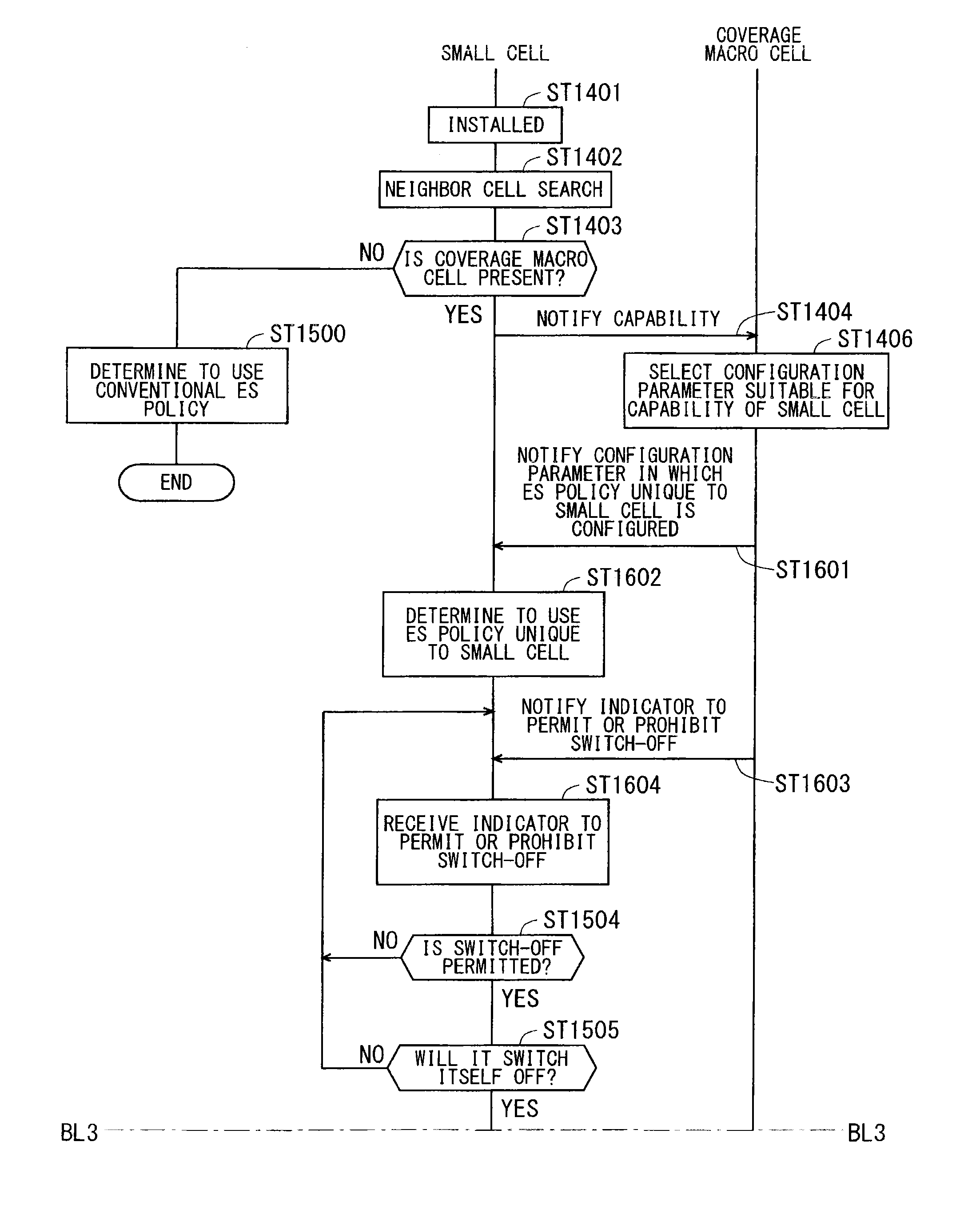
[0312]Described below is a solution solved in the second embodiment. 3GPP has discussed energy saving (ES) of infrastructure. For ES, cells such as a small cell and a macro cell are configured to switch between a state in which a normal operation described below is performed (also referred to as an “active state” or “on-state”) and a state in which an energy saving operation described below is performed (also referred to as a “dormant state” or “off-state”). Herein, the energy saving operation refers to an operation with reduced consumption energy compared with the normal operation. In the following description, the operation of switching from the on-state to the off-state may be referred to as “switch off,” whereas the operation of switching from the off-state to the on-state may be referred to as “switch on.”
[0313]Described below is the conventional ES policy. In the conventional ES policy, a cell switches itself off, specifically, shifts from the normal operation to the energy sa...
first modification
of Second Embodiment
[0410]A first modification of the second embodiment solves a problem similar to that of the second embodiment. Described below is a solution in the first modification of the second embodiment.
[0411]The first modification of the second embodiment newly provides the ES method unique to a small cell, which differs from the conventional method. Specifically, a switch-off method unique to a small cell and a method of requesting re-activation unique to a small cell are newly provided in the conventional ES policy. These methods do not newly provide an ES policy per se and thus avoid a communication system becoming more complicated than the method of newly providing an ES policy unique to a small cell of the second embodiment. Also, a communication system having excellent backward compatibility can be constructed. This achieves an ES operation optimum for a communication system in which small cells are introduced.
[0412]The solution in the first modification of the secon...
PUM
 Abstract
Description
Claims
Application Information
 - R&D
- Intellectual Property
- Life Sciences
- Materials
- Tech Scout
- Unparalleled Data Quality
- Higher Quality Content
- 60% Fewer Hallucinations
Browse by: Latest US Patents, China's latest patents, Technical Efficacy Thesaurus, Application Domain, Technology Topic, Popular Technical Reports.
© 2025 PatSnap. All rights reserved.Legal|Privacy policy|Modern Slavery Act Transparency Statement|Sitemap|About US| Contact US: help@patsnap.com


