
Omni-directional shear-horizontal wave electromagnetic acoustic transducer

Active Publication Date: 2016-01-07
SEOUL NAT UNIV R&DB FOUND
View PDF7 Cites 7 Cited by
  • Summary
  • Abstract
  • Description
  • Claims
  • Application Information

AI Technical Summary

Benefits of technology

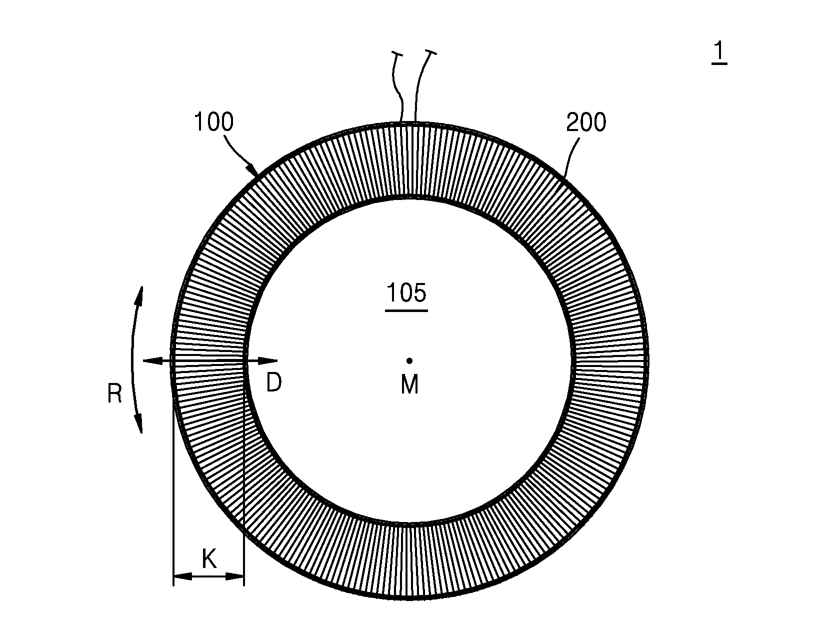
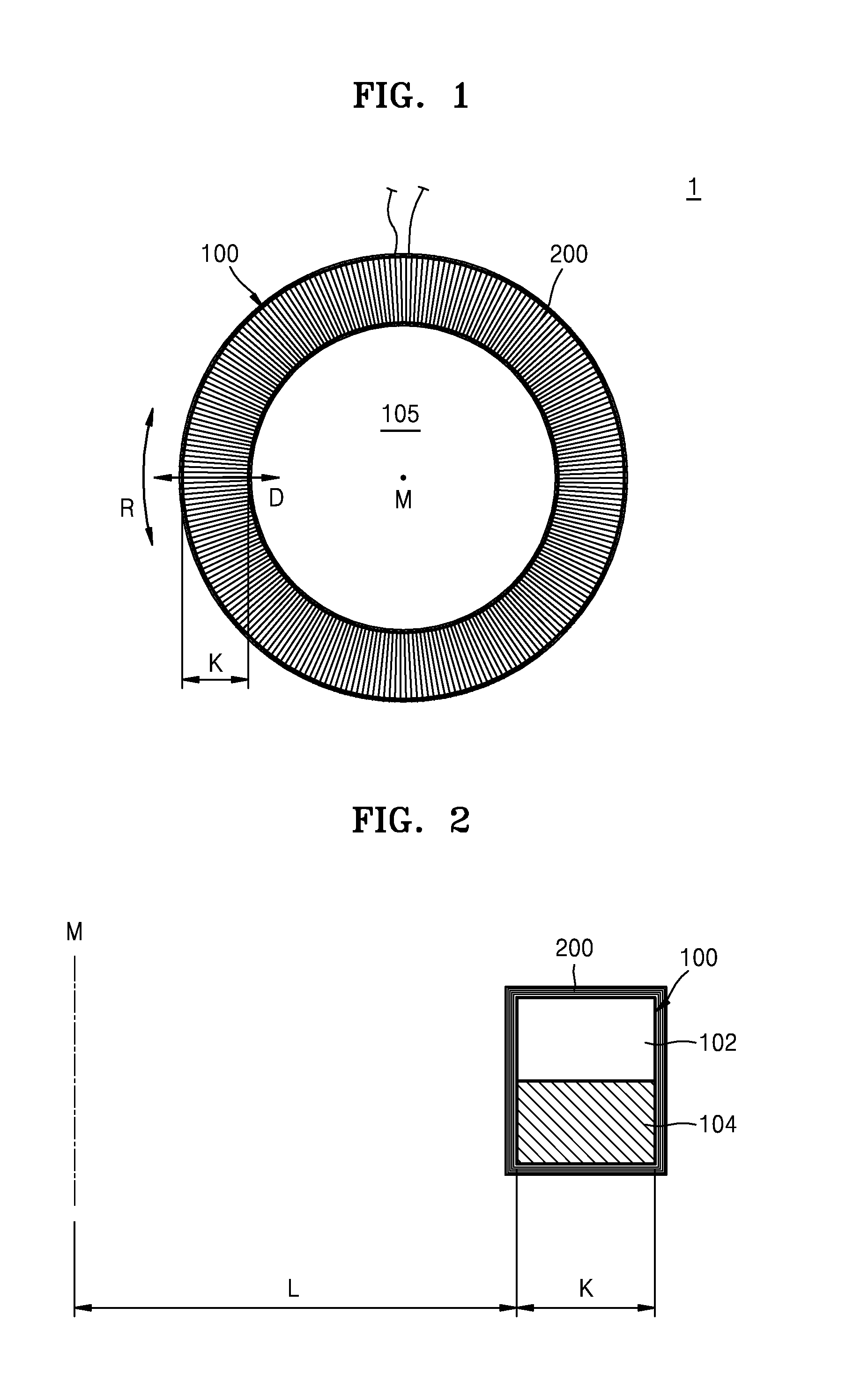
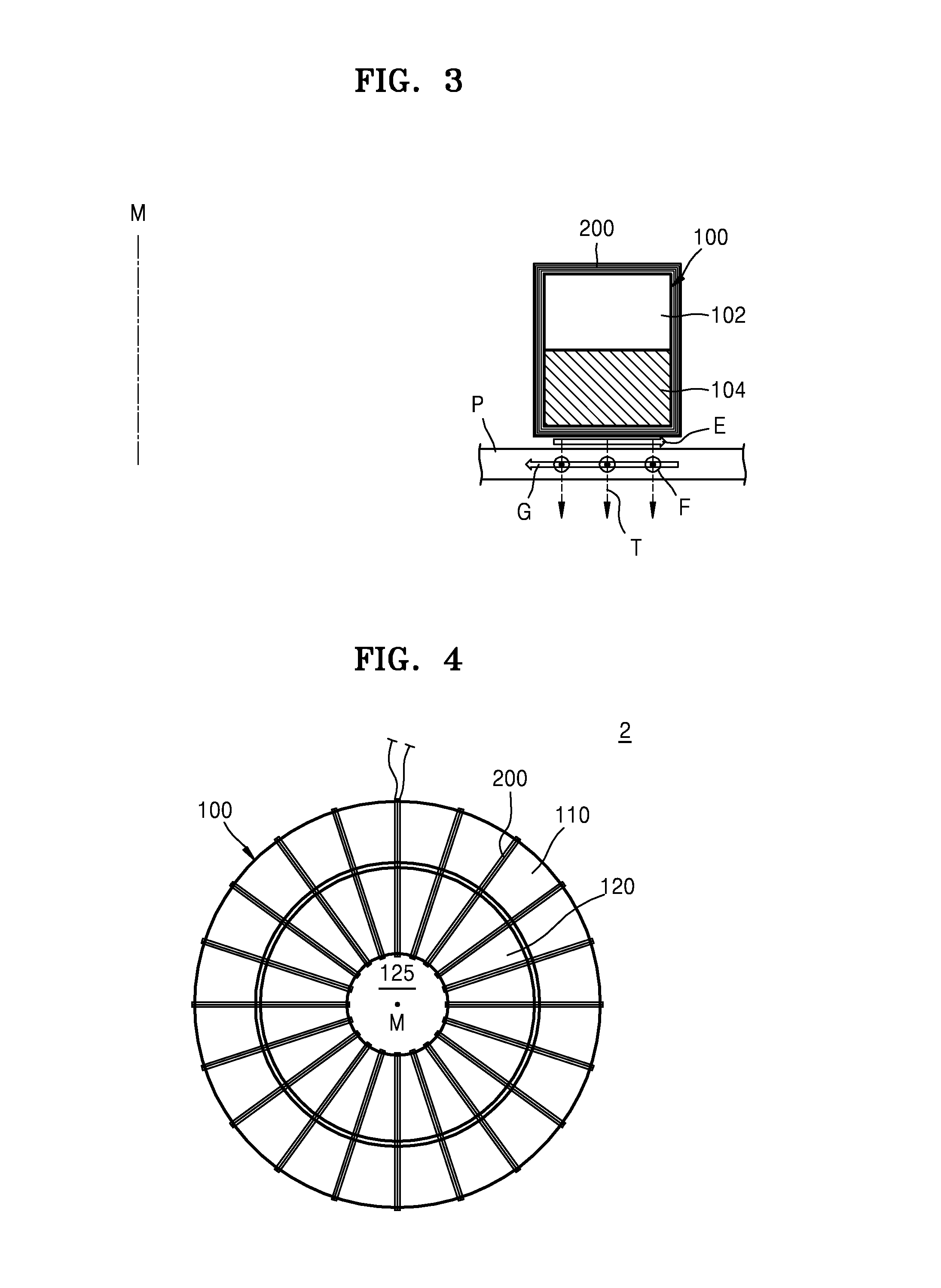
The invention is a transducer that includes a permanent magnet and a coil. The permanent magnet has a circular ring shape with upper and lower surfaces, and a circular through-portion in the middle. The coil is wound across an area between the inner surface of the through-portion and the outer surface of the magnet. The coil is made of conductive material, and an alternating current is applied to it. The direction of the current and the magnetic field passing through the coil are perpendicular to each other. The patent text also describes different configurations of the permanent magnet and coil, including the use of two permanent magnets and a coil with two winding portions. The technical effects of the invention include improved performance and efficiency of the transducer in generating magnetic flux and converting it into electrical current.

Problems solved by technology

However, typical omni-directional transducers generally generate and measure Lamb waves, which have several limitations in comparison with shear-horizontal waves, fundamental mode (SH0 mode) of which has non-dispersive property.

Method used


Image

  • Omni-directional shear-horizontal wave electromagnetic acoustic transducer
  • Omni-directional shear-horizontal wave electromagnetic acoustic transducer
  • Omni-directional shear-horizontal wave electromagnetic acoustic transducer

Examples


Embodiment Construction

[0031]Hereinafter, exemplary embodiments of the inventive concept will be described in detail with reference to the attached drawings. The embodiments are not intended to be limitative.

[0032]Advantages, features, and a method of achieving the same will be specified with reference to embodiments that will be described in detail with reference to the attached drawings. However, the inventive concept will not be limited to the embodiments described below and may be embodied in various different forms. Merely, the exemplary embodiments are provided to perfectly disclose the inventive concept and to allow one of ordinary skill in the art to fully understand the inventive concept. The inventive concept is defined by the scope of claims thereof. Through the entire specification, like reference numerals designate like elements.

[0033]Expressions of “the left”, “the right”, and “the side”, which are spatially relative, may be used to easily disclose correlations between one element or compone...


PUM

PropertyMeasurementUnit
widthaaaaaaaaaa
magnetic fluxaaaaaaaaaa
areaaaaaaaaaaa

Abstract

A transducer is provided. The transducer includes: a permanent magnet unit formed in a form of a circular ring having upper and lower surfaces each having a predetermined diametrical direction width while having a circular through-portion in a central portion of the permanent magnet unit, the permanent magnet unit generating a vertical magnetic flux due to opposite magnetic poles that are formed in the upper and lower surfaces; and a coil wound in a diametrical direction across an area between an inner surface formed by the circular through-portion of the permanent magnet and an outer surface formed by an outer circumference of the permanent magnet and also wound in a circumferential direction of the permanent magnet, wherein the coil comprises a conductive material so that a current is applied to the coil, and when an alternating current is applied to the coil, a direction of the alternating current flowing along the coil and a direction of a magnetic field passing through the coil are orthogonal to each other.

Description

RELATED APPLICATION[0001]This application claims the benefit of Korean Patent Application No. 10-2014-0082535, filed on Jul. 2, 2014, in the Korean Intellectual Property Office, the disclosure of which is incorporated herein in its entirety by reference.BACKGROUND[0002]1. Field[0003]The inventive concept relate to a transducer, and more particularly, to an omni-directional shear-horizontal wave electromagnetic acoustic transducer.[0004]2. Description of the Related Art[0005]Since omni-directional transducers may generate waves having the same magnitude and mode in all directions, when applying omni-directional transducers to phased array systems, it is possible to efficiently focus waves by using the same algorithm with respect to all directions. However, typical omni-directional transducers generally generate and measure Lamb waves, which have several limitations in comparison with shear-horizontal waves, fundamental mode (SH0 mode) of which has non-dispersive property. Accordingly...

Claims


Application Information

Patent Timeline
Patent Type & Authority Applications(United States)
IPC IPC(8): G01N29/24
CPCG01N2291/0422G01N29/2412G01N2291/0427
Inventor SEUNG, HONG MINKIM, YOON YOUNG
Owner SEOUL NAT UNIV R&DB FOUND
Learn More