Dynamic microphone and method of forming back-side air chamber

a back-side air chamber and microphone technology, applied in the field of dynamic microphones, can solve the problems of unrealistic infinite expansion of the back-side air chamber volume, limited volume of the back-side air chamber, handheld dynamic microphones, etc., and achieve the effect of suppressing the free vibration of the wall

Inactive Publication Date: 2015-12-31
AUDIO-TECHNICA
View PDF12 Cites 7 Cited by
  • Summary
  • Abstract
  • Description
  • Claims
  • Application Information

AI Technical Summary

Benefits of technology

The present invention provides a dynamic microphone with a large back-side air chamber that efficiently uses the volume inside the grip case and prevents the generation of standing waves. The acoustic resistance body formed of metal fiber has an open cross sectional area gradually decreasing toward the direction remote from the dynamic microphone unit, which effectively avoids the generation of standing waves in the back-side air chamber. The metal fiber is pressingly attached to, and in tight contact with, the internal surface of the case constituting the back-side air chamber, suppressing the free vibration of the wall constituting the case. This dynamic microphone effectively avoids the wall of the back-side air chamber having a certain resonance frequency.

Problems solved by technology

It is unrealistic to infinitely increase the volume of the back-side air chamber.
Handheld dynamic microphones, in particular, have more strict limitation on the volume of the back-side air chamber.
However, the dynamic microphone disclosed in JP 3882268 B1 is disadvantageous in that the volume of the air chamber is limited because the back-side air chamber is formed, for example, in a conical shape.

Method used


Image

  • Dynamic microphone and method of forming back-side air chamber
  • Dynamic microphone and method of forming back-side air chamber
  • Dynamic microphone and method of forming back-side air chamber

Examples


Embodiment Construction

[0032]A dynamic microphone according to the present invention will be described based on an embodiment illustrated in the drawings.

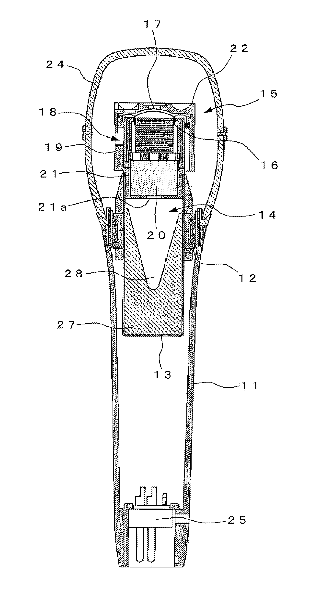
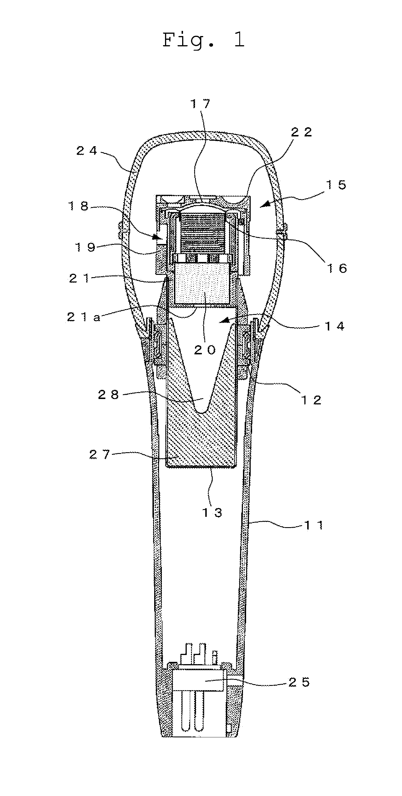
[0033]FIG. 1 illustrates a first embodiment. The example illustrated in FIG. 1 is mainly used by a vocalist and a person making a speech, and includes a cylindrical grip case 11 made of, for example, a brass alloy.

[0034]A bottomed case 13 formed of, for example, an aluminum material is coaxially attached inside the grip case 11 via a shock-mount member 12 made of an elastic rubber part. The bottomed case 13 constitutes the back-side air chamber 14 of the dynamic microphone unit as will be described below.

[0035]A dynamic microphone unit 15 is attached to the front end of the case 13. The dynamic microphone unit 15 is known to include a diaphragm 17 including a voice coil 16 and a magnetic circuit 18 including a magnetic gap in which the voice coil 16 is disposed so as to vibrate. The microphone unit 15 is attached with the outer periphery of a yoke consti...


PUM


Abstract

A dynamic microphone which prevents a wall forming a back-side air chamber from having a certain resonance frequency and effectively prevents the generation of standing waves in the back-side air chamber is provided. A dynamic microphone includes a dynamic microphone unit including a diaphragm configured with a voice coil and a magnetic circuit having a magnetic gap provided so as to allow the voice coil to vibrate, a bottomed case which is coupled to the dynamic microphone unit and forms a back-side air chamber communicating with back side of the diaphragm, and an acoustic resistance body which is pressingly attached in the case and composed of metal fiber including a pocket, an open cross sectional area of the pocket gradually decreasing toward the direction remote from the dynamic microphone unit.

Description

BACKGROUND OF THE INVENTION[0001]1. Field of the Invention[0002]The present invention relates to a dynamic microphone having an improved air chamber formed in the back portion of a dynamic microphone unit and a method of forming a back-side air chamber.[0003]2. Description of the Related Art[0004]It is well-known that the omnidirectional dynamic microphone operates by resistance control and the unidirectional dynamic microphone operates by mass control and resistance control.[0005]The resistance control of the dynamic microphone is carried out by an acoustic resistance provided very close to the back side of a diaphragm and a back-side air chamber, in which no acoustic wave enters, provided in the back side of the acoustic resistance. The acoustic resistance is located at the inlet of the back-side air chamber. When the volume of the back-side air chamber is significantly large, the total impedance of the acoustic resistance and the impedance of the air chamber is substantially equi...

Claims


Application Information

Patent Timeline
Patent Type & Authority Applications(United States)
IPC IPC(8): H04R1/22H04R9/02H04R9/08H04R31/00
CPCH04R1/2876H04R9/08H04R31/00
Inventor AKINO, HIROSHI
Owner AUDIO-TECHNICA
Why Eureka
Try Eureka