Centralized power distribution member for motor

a technology of centralized power distribution and motor, which is applied in the direction of dynamo-electric machines, electrical apparatus, windings, etc., can solve the problems of not being able to deal with space, and achieve the effects of reducing space occupation, reducing leakage, and maintaining connection operability

Active Publication Date: 2015-12-24
SUMITOMO WIRING SYST LTD +1
View PDF10 Cites 5 Cited by
  • Summary
  • Abstract
  • Description
  • Claims
  • Application Information

AI Technical Summary

Benefits of technology

[0014]Since a sealing structure by the rubber rings is adopted, leakage can be inexpensively dealt with, for example, as compared with sealing by potting of adhesive.
[0015]According to the centralized power distribution member of the present invention, it is possible to realize space saving in a radial direction by suppressing a radially outward bulging amount of an annular holder while satisfactorily maintaining connection operability in a power feeding unit.

Problems solved by technology

This cannot be dealt with in terms of space in some cases.

Method used


Image

  • Centralized power distribution member for motor
  • Centralized power distribution member for motor
  • Centralized power distribution member for motor

Examples


Embodiment Construction

[0029]One embodiment of the present invention is described based on FIGS. 1 to 13.

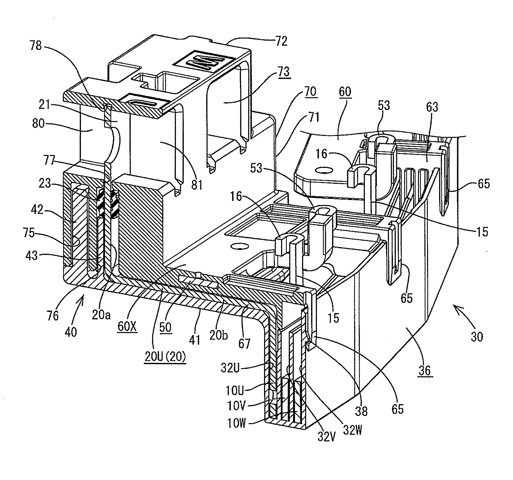
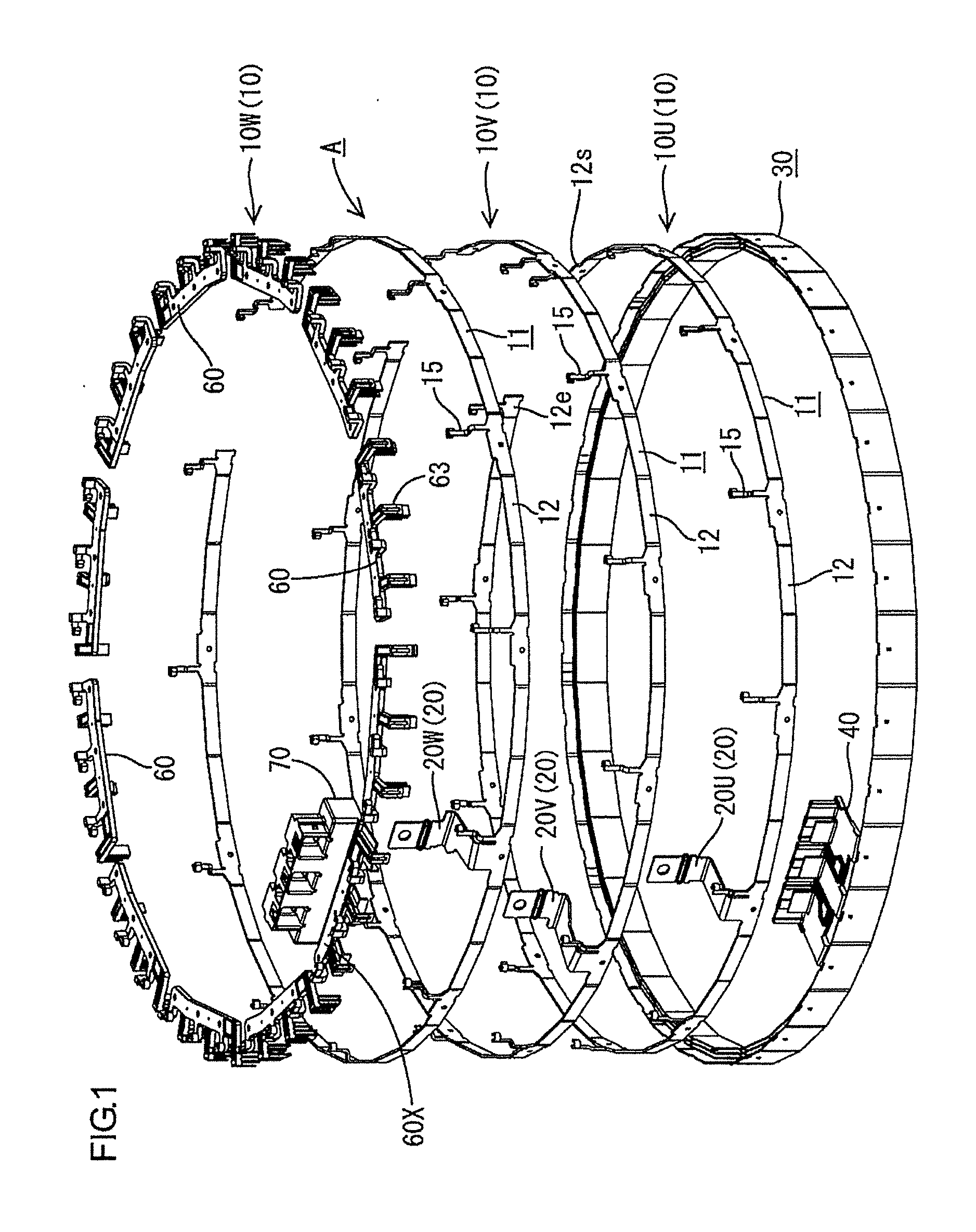
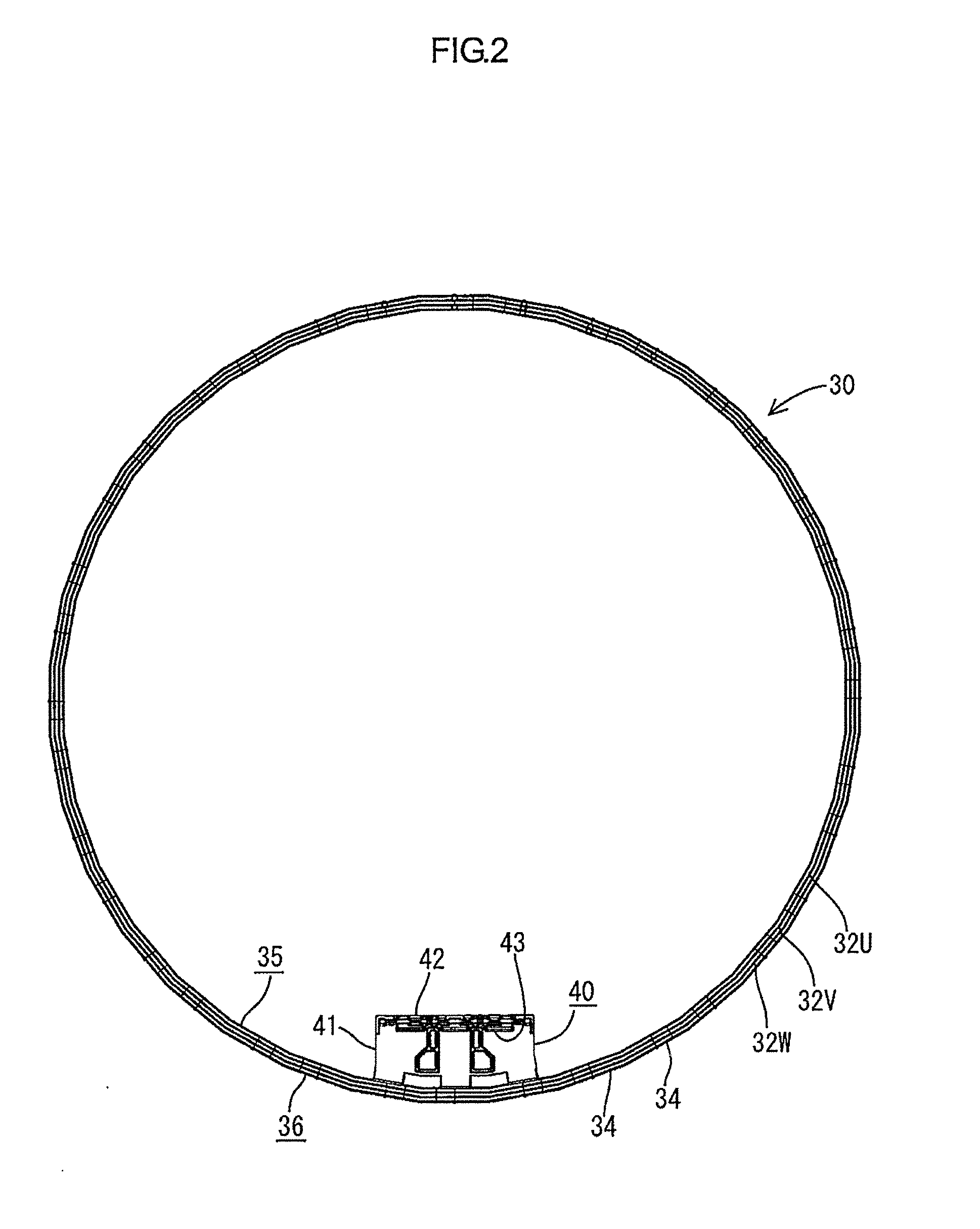
[0030]A motor of this embodiment is a three-phase alternating current brushless motor with 12 pole pairs to be mounted in a hybrid vehicle and is arranged, for example, in a narrow space between an engine and a transmission and includes a rotor (not shown) coaxially coupled to a horizontal crankshaft of the engine, an annular stator S (see FIG. 7) concentrically surrounding the rotor and an annular centralized power distribution member A concentrically surrounding the stator S. The stator S is composed of a plurality of magnetic poles (not shown) formed by winding coils on cores, the magnetic poles are arranged at fixed intervals along a circumference concentric with the rotor, opposite end parts of a winding are drawn out from each magnetic pole and a star connection method is adopted.

[0031]The centralized power distribution member A is for feeding power to the windings of the stator S and includes, a...


PUM


Abstract

A centralized power distribution member A for motor arranged on the outer periphery of a stator S of a motor and configured to feed power to windings of the stator S includes a plurality of annular busbars 10 each including a power feeding terminal 20 and connection terminals 15 to the windings on one side edge, an annular holder 30 made of synthetic resin and configured to accommodate the busbars 10 laminated in a radial direction in a mutually insulated manner, and a power feeding unit 70 arranged near a predetermined position in a circumferential direction and individually connected to the power feeding terminal 20 of each busbar 10 and power supply side terminals drawn out from a power supply side. The power feeding unit 70 is arranged on an end surface side of the stator S where the power feeding terminals 20 and the connection terminals 15 are arranged.

Description

BACKGROUND[0001]1. Field of the Invention. The present invention relates to a centralized power distribution member for motor.[0002]2. Description of the Related Art. An example of a centralized power distribution member for feeding power to windings of a stator of a three-phase motor is known from Japanese Unexamined Patent Publication No. 2003-134759 below. This is provided with three annular busbars each including one power feeding terminal to be connected to a power supply and a plurality of connection terminals to be connected to windings of respective U-, V- and W-phases on one side edge and having different radial dimensions and an annular holder made of resin in which as many accommodation grooves as the busbars are concentrically provided, and structured such that the respective busbars laminated in a radial direction in a mutually insulated manner are accommodated by being inserted into the corresponding accommodation grooves of the annular holder.[0003]On the other hand, ...

Claims


Application Information

Patent Timeline
Patent Type & Authority Applications(United States)
IPC IPC(8): H02K3/50
CPCH02K3/50H02K15/0025H02K3/522H02K2203/09H02K3/38
Inventor HASHIMOTO, TSUTOMUFUKAHORI, SATOSHI
Owner SUMITOMO WIRING SYST LTD
Why Eureka
Try Eureka