Mold frame, backlight module and display device

a backlight module and display device technology, applied in the field of display, can solve the problems of light leakage wrinkling of optical films, etc., and achieve the effect of reducing friction, reducing phenomena, and low light incidence efficiency of the backlight modul

Active Publication Date: 2015-12-17
BOE TECH GRP CO LTD +1
View PDF2 Cites 2 Cited by
  • Summary
  • Abstract
  • Description
  • Claims
  • Application Information

AI Technical Summary

Benefits of technology

[0012]In some alternative embodiments, the plurality of rollers are equidistantly distributed. The equidistantly-distributed rollers may better limit the light guide plate.
[0013]In some alternative embodiments, the rollers are made of a rubber material. The rollers of the rubber material may reduce friction between the rollers and the light guide plate.
[0014]The present disclosure further provides a backlight module, comprising: a light guide plate, a light source and optical films, and further comprising the mold frame as recited above, wherein the light guide plate, the light source and the optical films are located in the mold frame. A diameter of the rollers provided in the mold frame is substantially equal to a sum of a predetermined distance between the mold frame and the light guide plate and a depth of the recess provided in the mold frame. The mold frame according to the present disclosure may reduce occurrence of phenomena such as low light incidence efficiency of the backlight module, light leakage of the backlight module and wrinkling of the optical films. The display module according to the present disclosure has a higher light utilization rate.
[0015]The present disclosure further provides a display device comprising a display panel and the aforesaid backlight module. Since the backlight module has a higher light utilization rate, the display device according to the present disclosure achieves a better display effect.

Problems solved by technology

5), thereby causing occurrence of phenomena such as low light incidence efficiency of the backlight module, light leakage of the backlight module and wrinkling of the optical films.

Method used


Image

  • Mold frame, backlight module and display device
  • Mold frame, backlight module and display device
  • Mold frame, backlight module and display device

Examples


embodiment 1

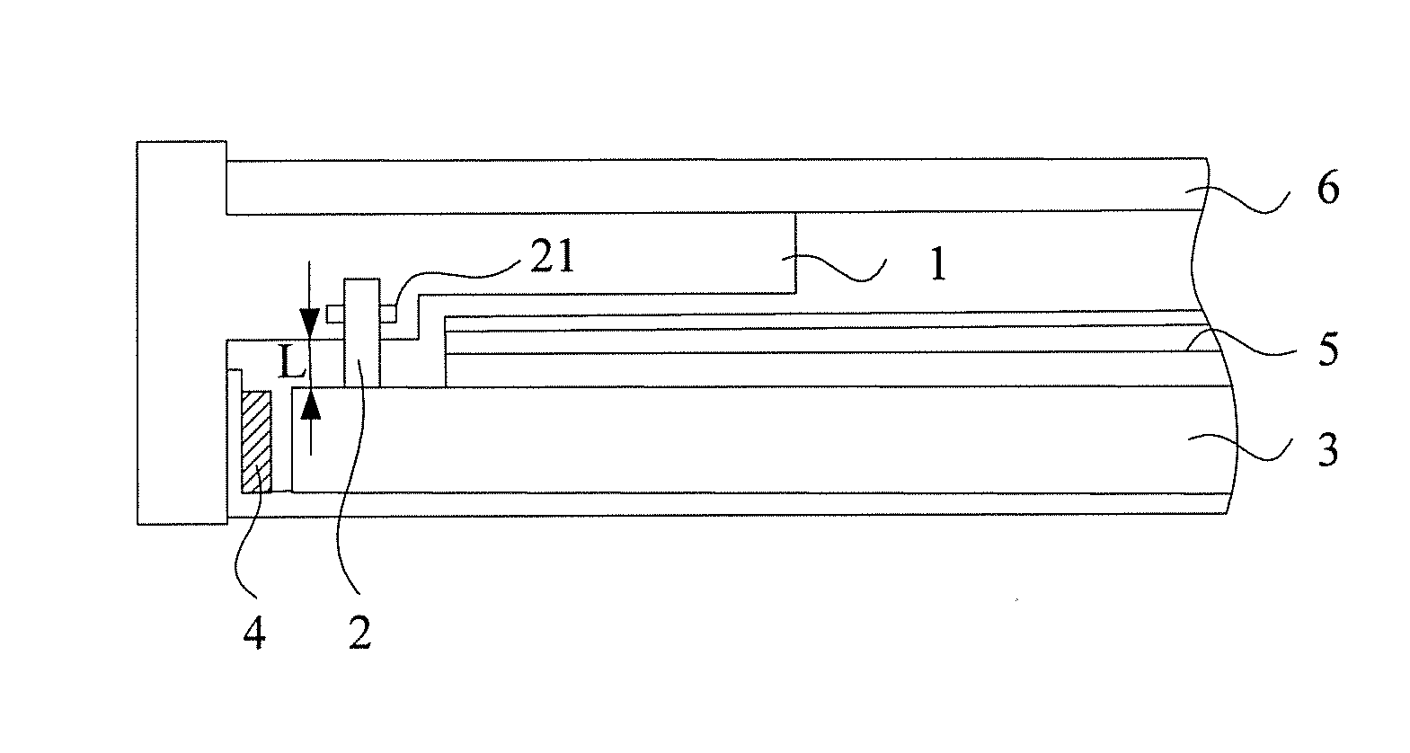
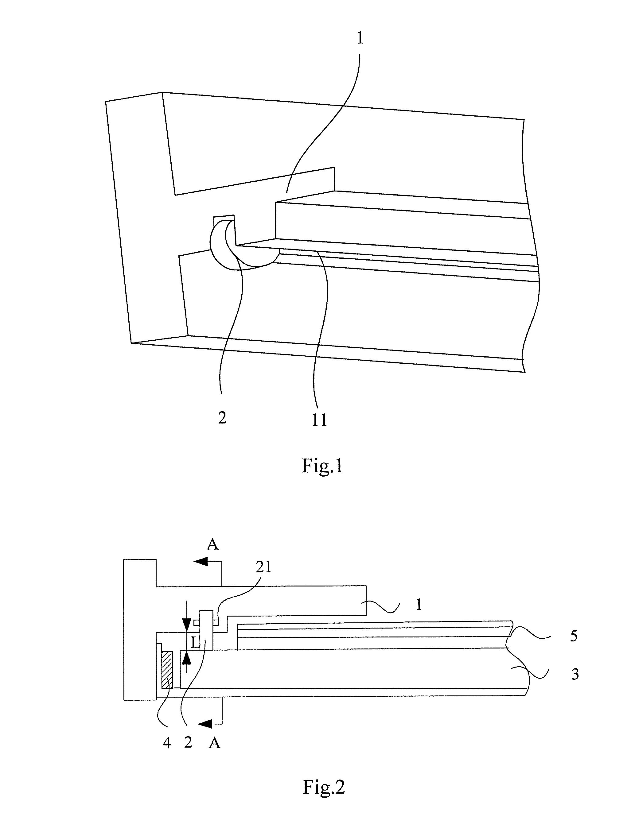
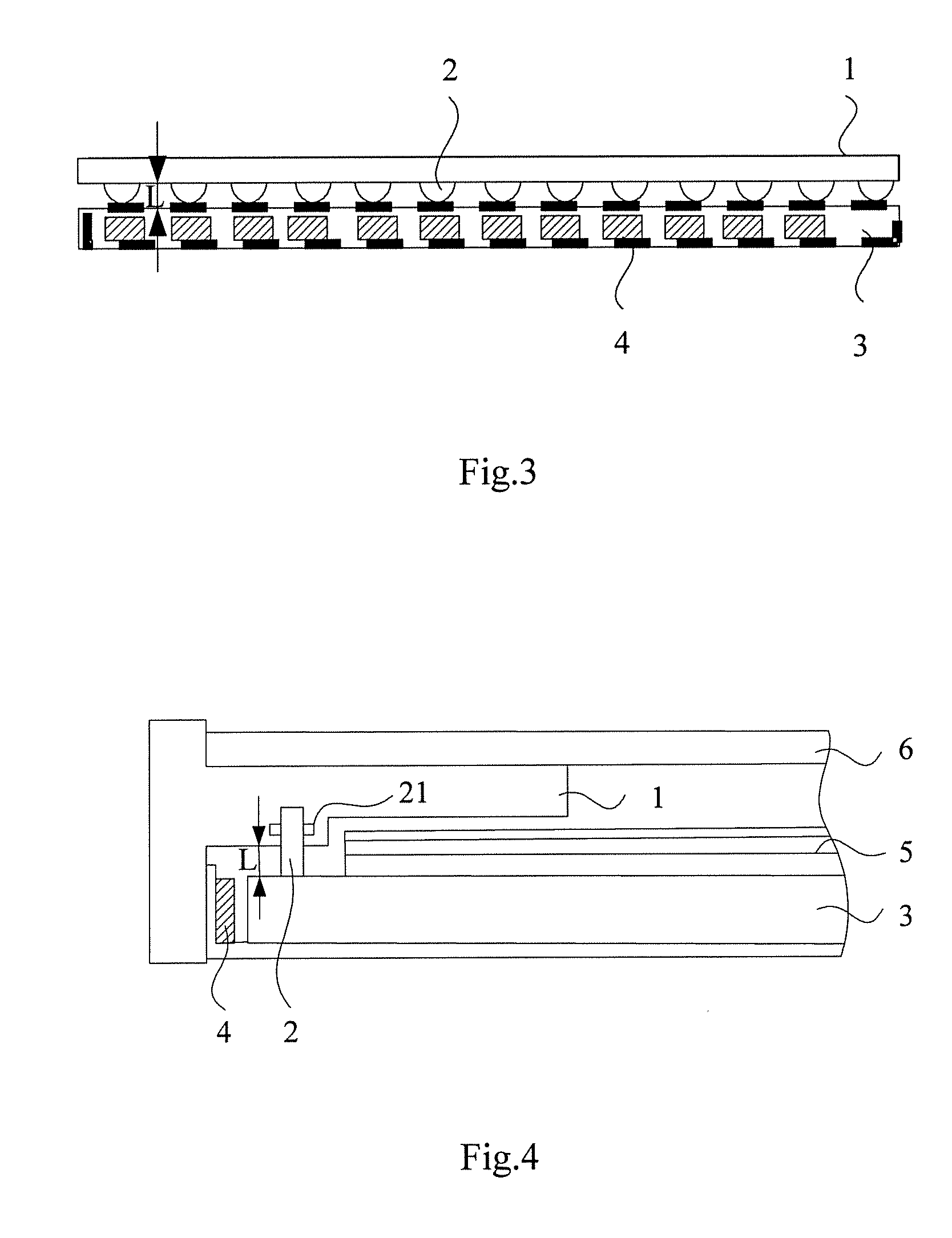
[0032]As shown in FIG. 2, the present disclosure further provides a backlight module, comprising: a light guide plate 3, a light source 4 and optical films 5 and the mold frame as recited in the above embodiment 1. The light guide plate 3, the light source 4 and the optical films 5 are located in the mold frame. A diameter of the rollers 2 provided in the mold frame is substantially equal to a sum of a predetermined distance L between the mold frame and the light guide plate and a depth of the recess 11 provided in the mold frame.

[0033]The mold frame according to the present disclosure may reduce occurrence of phenomena such as light leakage of the backlight module and wrinkling of the optical films. The display module according to the present disclosure has a higher light utilization rate.

embodiment 2

[0034]FIG. 4 is a structural schematic view of a display device provided by an embodiment of the present disclosure. As shown in FIG. 4, the present disclosure further provides a display device, comprising a display panel 6 and the backlight module as recited in the above embodiment 2.

[0035]Since the above-mentioned backlight module has a higher light utilization rate, the display device according to the present disclosure achieves a better display effect.


PUM


Abstract

The present disclosure discloses a mold frame, a backlight module and a display device. The mold frame includes sidewalls for limiting a periphery of a light guide plate and optical films in the backlight module, and a boss for limiting the light guide plate and the optical films in a direction perpendicular to an output surface of the light guide plate. The boss is provide with a recess opening towards the light guide plate. The recess is provided with a number of rollers therein in a lengthwise direction thereof. A diameter of the rollers is greater than a depth of the recess. The mold frame is applied to the backlight module. In assembly, the light guide plate, the light source and the optical films are placed in the mold frame. An outside surface of the roller provided in the boss of the mold frame abuts against the light guide plate, limiting the light guide plate in the direction of the thickness of the backlight module, thereby preventing the light guide plate from warping upward after expansion due to heat. Hence, the mold frame according to the present disclosure may reduce occurrence of phenomena such a slow light incidence efficiency of the backlight module, light leakage of the backlight module and wrinkling of the optical films.

Description

RELATED APPLICATIONS[0001]The present application claims the benefit of Chinese Patent Application No. 201410268844.4, filed Jun. 17, 2014, the entire disclosure of which is incorporated herein by referenceBACKGROUND OF THE DISCLOSURE[0002]1. Field of the Disclosure[0003]The present disclosure relates to the technical field of display, and particularly to a mold frame, a backlight module and a display device.[0004]2. Description of the Prior Art[0005]As display technologies develop constantly, people have higher and higher requirements for display devices.[0006]A liquid crystal display device in the prior art is structured as shown in FIG. 5, and it mainly comprises a display panel 01 and a backlight module, wherein the backlight module specifically comprises a mold frame 02, a back plate 06, a light guide plate 03 located between the mold frame 02 and the back plate 06, optical film layers 04 located on an output side of the light guide plate 03, and a light source 05 located at a ...

Claims


Application Information

Patent Timeline
Patent Type & Authority Applications(United States)
IPC IPC(8): F21V8/00
CPCG02B6/0088G02B6/005G02B6/0065G02B6/0091
Inventor JIA, ZHISHUAIFU, CHANGJIALI, SHAOAN
Owner BOE TECH GRP CO LTD
Why Eureka
Try Eureka