
Antenna system and method of assembly for a wearable electronic device

a technology of electronic devices and antennas, applied in the field of antenna systems for wearable electronic devices, can solve problems such as compromising the effectiveness of antennas

Active Publication Date: 2015-12-03
GOOGLE TECH HLDG LLC
View PDF3 Cites 60 Cited by
  • Summary
  • Abstract
  • Description
  • Claims
  • Application Information

AI Technical Summary

Benefits of technology

The present patent is about an antenna system for a wearable electronic device. The system includes a first conductive surface made from a segment of the device's outer housing, and a second conductive surface made from internal components. The two surfaces are separated by a space. The system also includes a contact element with a feeding element that connects the first conductive surface to the second conductive surface along a plane that is normal to the first conductive surface. The technical effect of this design is that it allows for a more aesthetically appealing wearable electronic device that maintains high performance in electronic performance.

Problems solved by technology

One shortcoming, however, in such devices is a tradeoff between stylish appearance and electronic performance.
If the antenna emanates signals outside of this frequency range, the effectiveness of the antenna is compromised.

Method used


Image

  • Antenna system and method of assembly for a wearable electronic device
  • Antenna system and method of assembly for a wearable electronic device
  • Antenna system and method of assembly for a wearable electronic device

Examples


Embodiment Construction

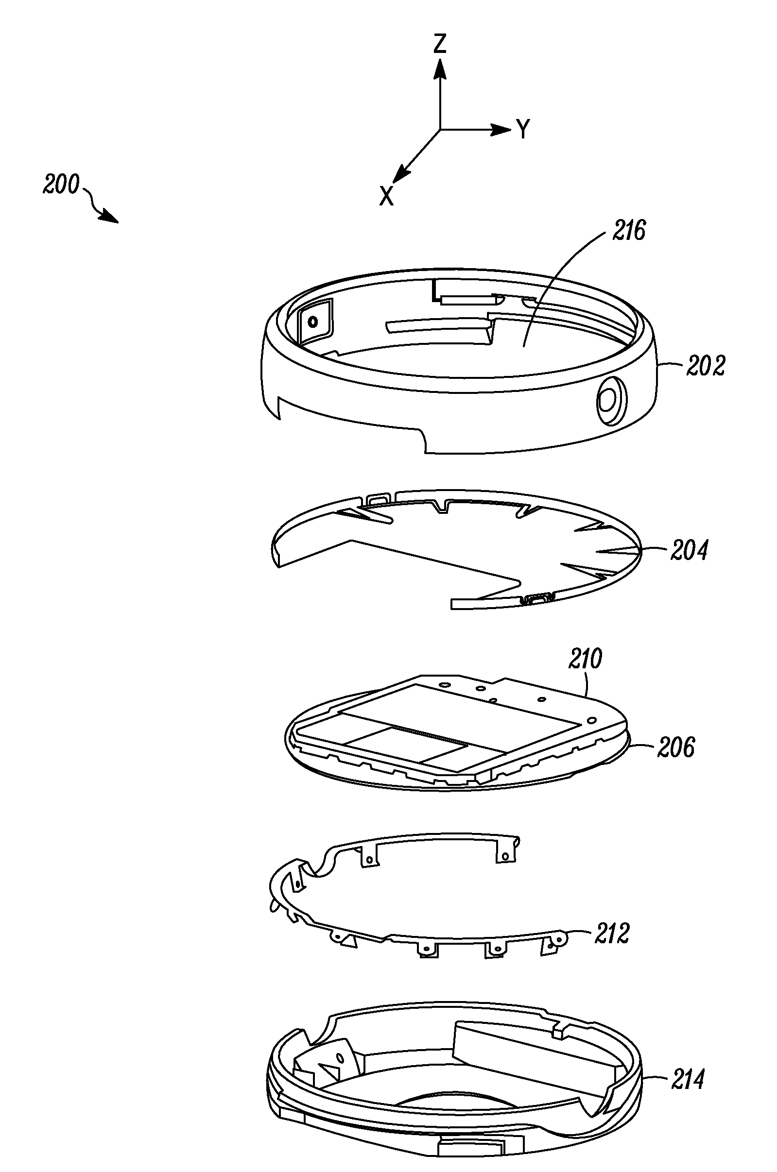
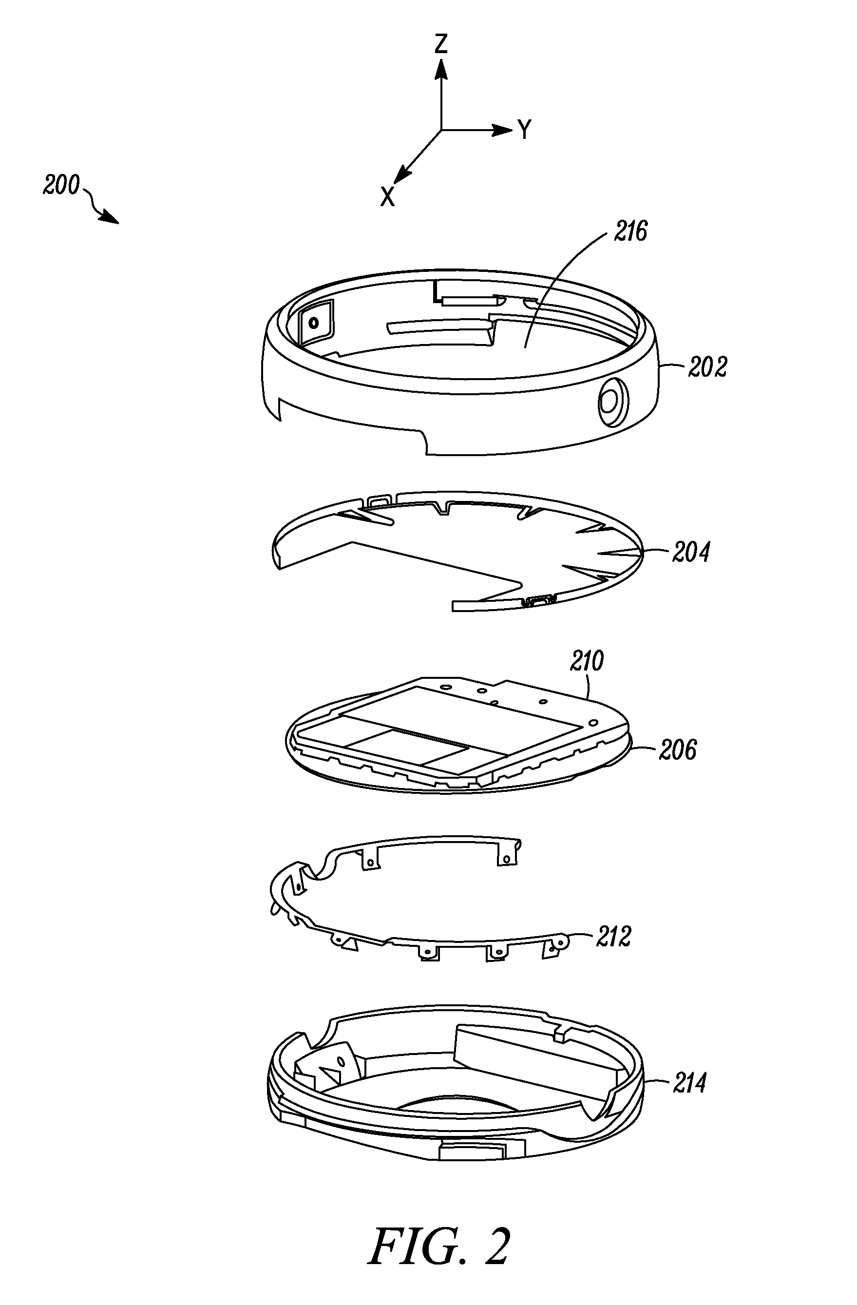
[0016]Generally speaking, pursuant to the various embodiments, the present disclosure provides for an antenna system for a wearable electronic device. In one example embodiment, the antenna system includes a first conductive surface constructed from a segment of outer housing of the wearable electronic device. The first conductive surface spans a first axis through the wearable electronic device. The antenna system also includes a second conductive surface that spans the first axis. The second conductive surface is constructed from a set of contacting metal components that are internal to the wearable electronic device. The first and second conductive surfaces are separated by a space. In one example embodiment, the antenna system also includes a contact element having a feeding element that connects the first conductive surface to the second conductive surface along a plane that is normal to the first conductive surface.

[0017]In another implementation, a wearable electronic device ...


PUM

PropertyMeasurementUnit
Shapeaaaaaaaaaa
Electrical conductoraaaaaaaaaa
Dimensionaaaaaaaaaa

Abstract

An antenna system for a wearable electronic device includes a first conductive surface constructed from a segment of outer housing of the wearable electronic device. The first conductive surface spans a first axis through the wearable electronic device. The antenna system also includes a second conductive surface that spans the first axis. The second conductive surface is constructed from a set of contacting metal components that are internal to the wearable electronic device. The first and second conductive surfaces are separated by a space. The antenna system also has a contact element having a feeding element that connects the first conductive surface to the second conductive surface along a plane that is normal to the first conductive surface.

Description

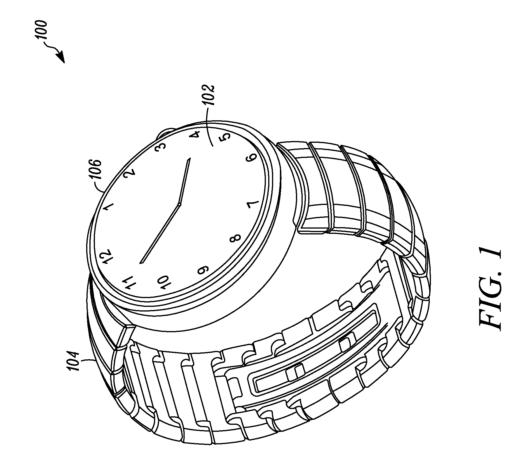
RELATED APPLICATIONS[0001]The present application is related to and claims benefit under 35 U.S.C. §119(e) from U.S. Provisional Patent Application Ser. Nos. 62 / 006,316 filed Jun. 2, 2014 and 62 / 016,884 filed Jun. 25, 2014, the entire contents of each being incorporated herein by reference.FIELD OF THE DISCLOSURE[0002]The present disclosure relates to an antenna system for a wearable electronic device and more particularly to an antenna system constructed from an outer housing of the wearable electronic device.BACKGROUND[0003]As electronics evolve, items that are commonly worn on a person's body are adapted to perform additional functions. For example, some wristwatches and eyeglasses are fitted with electronics to perform functions such as visual recordings and wireless transmission. One shortcoming, however, in such devices is a tradeoff between stylish appearance and electronic performance. More particularly, for some electronics, high performance is achieved at the expense of co...

Claims


Application Information

Patent Timeline
IPC IPC(8): H01Q1/27G04R60/06H01Q13/10
CPCH01Q1/273Y10T29/4902G04R60/06H01Q13/10G04G21/04
Inventor RUSSELL, MICHAEL E.COLES, KATHERINE H.SAYEM, ABU T.
Owner GOOGLE TECH HLDG LLC
Learn More