
Linear Motion Conveyor

Active Publication Date: 2015-11-26
KII TEKU INC
View PDF2 Cites 5 Cited by
  • Summary
  • Abstract
  • Description
  • Claims
  • Application Information

AI Technical Summary

Benefits of technology

The present invention relates to a linear motion conveyor that includes a reciprocal conveyor bed and a drive assembly. The drive assembly is positioned below the conveyor bed and is selectively movable in two directions to cause the conveyor bed to move the product in a first direction, a second direction, and to stop the movement of the product. The conveyor bed has a product transporting surface and a frame that supports it in spaced relation to a stationary base. A counter-weight is also included to move the product along the conveyor bed. The drive assembly is selectively positionable to further move the product in a third direction. The invention allows for precise movement of the product along the conveyor bed.

Problems solved by technology

Further, such prior art conveyors have tended to generate much more noise, and vibration than what their advocates will readily admit.
Additionally, and because of the physical relationships which exist between the various parts of these prior art conveyors, such prior art conveying arrangements are not readily adjustable so as to provide different conveying speeds, directions of movement, or which further can be readily adjusted so as to either slow down or stop the movement of product along the linear motion conveyor in the event that problems in a production line work station which is located downstream from the linear motion conveyor would require such stoppage of the product motion.

Method used


Image

  • Linear Motion Conveyor
  • Linear Motion Conveyor
  • Linear Motion Conveyor

Examples


Embodiment Construction

[0030]This disclosure of the invention is submitted in furtherance of the constitutional purposes of the U.S. Patent Laws “to promote the progress of science and useful arts” (Article 1, Section 8).

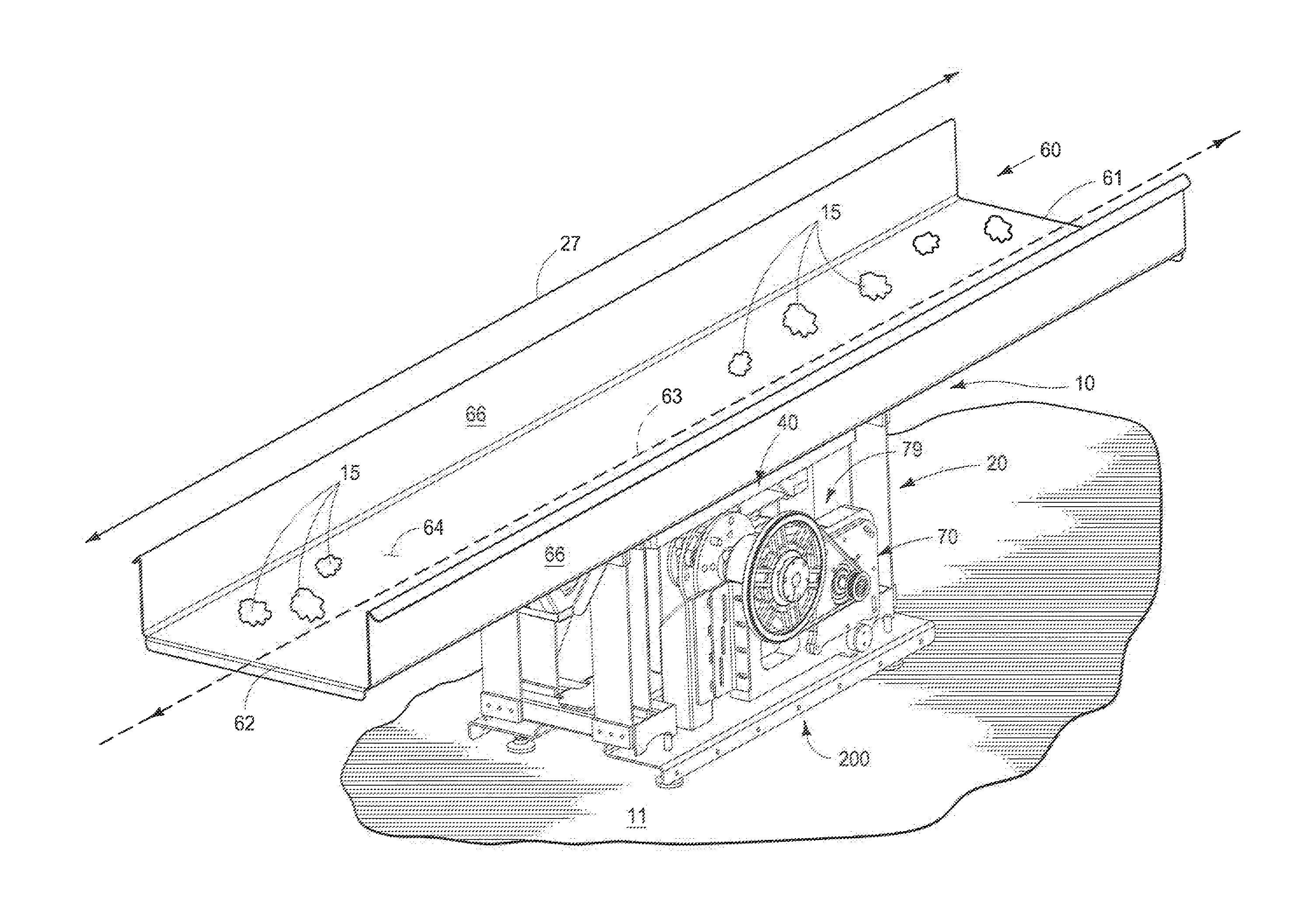
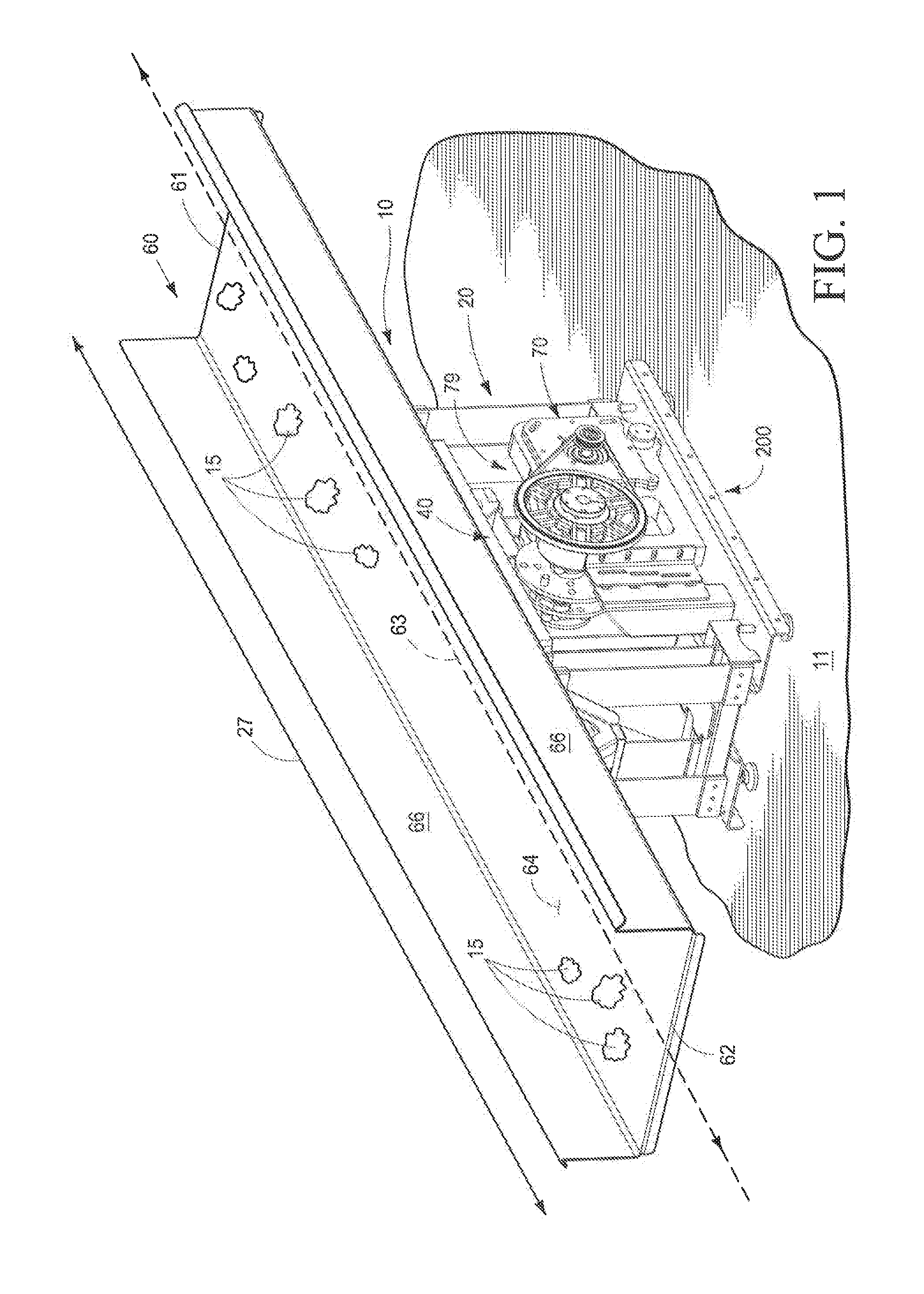
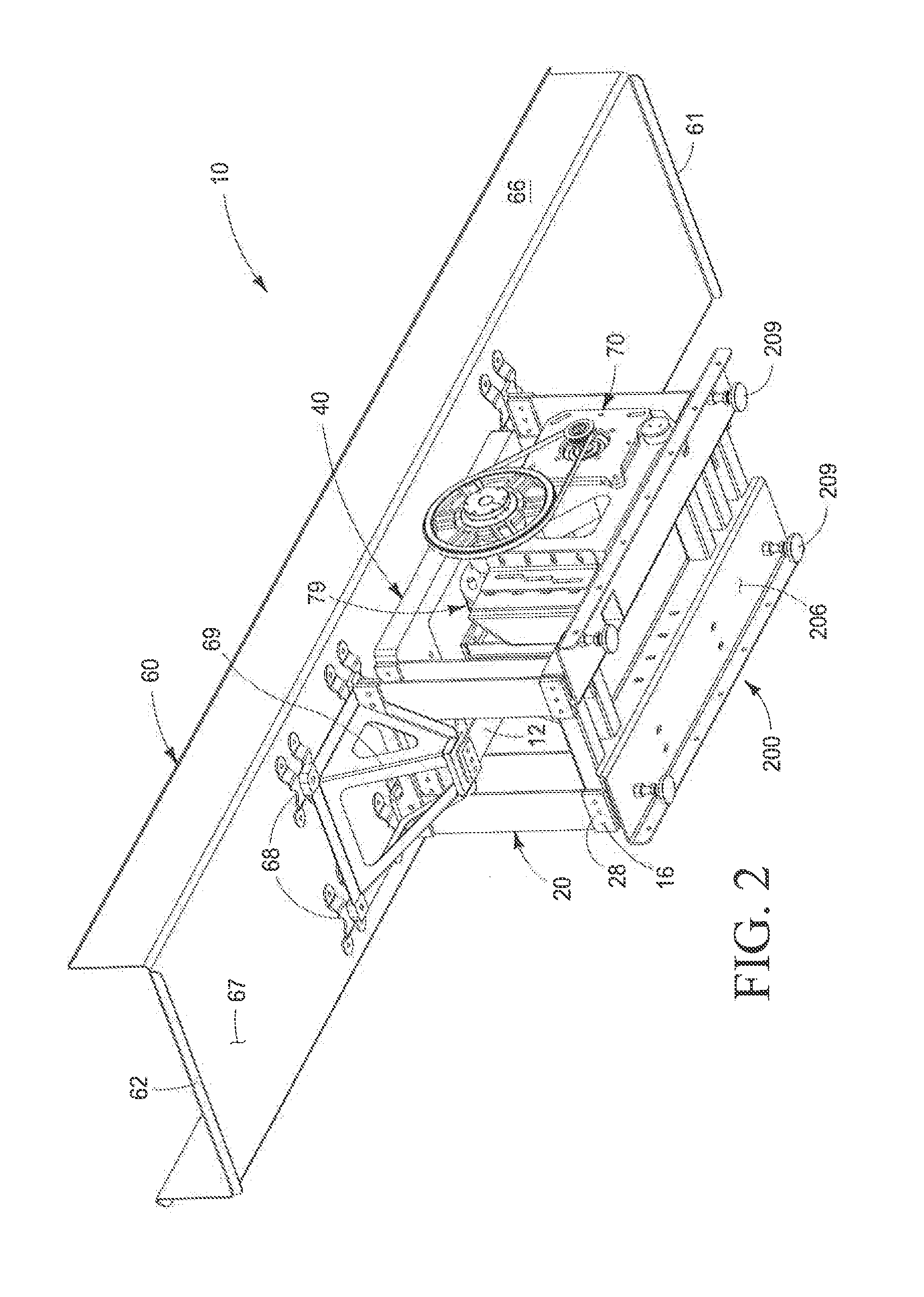
[0031]The improved linear motion conveyor of the present invention 10 generally comprises a stationary base 200, a drive assembly 79, a frame assembly 20, a counterweight 40, and an elongated conveyor bed 60.

[0032]The improved linear motion conveyor of the present invention is generally indicated by the numeral 10 in FIG. 1 and following. The invention 10 is supported on the stationary base 200 which, in turn, rests upon an underlying supporting surface which is generally indicated by the numeral 11. The underlying supporting surface may comprise a supporting floor of a factory, or other supporting surface located therebeneath.

[0033]The stationary base 200 (FIGS. 3, 3A) is generally rectilinear in configuration and has a first end portion 201; a second end portion 202; a first side portio...


PUM


Abstract

A linear motion conveyor is described and which includes an elongated conveyor bed having a product transporting surface for supporting and transporting a product between the opposite first and second ends thereof, and a drive assembly oriented in force transmitting relation relative to the elongated conveyor bed, and where the elongated conveyor bed, when reciprocated by the drive assembly is operable to move product alternatively between the opposite ends of the product elongated conveyor bed in a first direction; a second direction; and which is further rendered operable to substantially stop the movement of the product located between the opposite ends of the elongated conveyor bed.

Description

RELATED APPLICATIONS[0001]This utility patent application is a Continuation in Part (CIP) of prior filed and currently pending U.S. application Ser. No. 13 / 892,519 titled LINEAR MOTION CONVEYOR filed on May 13, 2013 by at least one of the same inventors, Eugene Groenewald. The entire contents of the aforementioned prior filed U.S. application Ser. No. 13 / 892,519 is expressly incorporated herein by this reference.TECHNICAL FIELD[0002]The present invention relates to a linear motion conveyor, and more specifically to a linear motion conveyor having a drive assembly which may be readily and selectively adjusted so as to impart motion to a product being transported by the linear motion conveyor, in opposite first and second directions, or to further stop the motion of product along the linear motion conveyor.BACKGROUND OF THE INVENTION[0003]Various conveying arrangements and devices have been devised and employed through the years for conveying products of various types along predetermi...

Claims


Application Information

Patent Timeline
IPC IPC(8): B65G27/20B65G27/32B65G27/30
CPCB65G27/20B65G27/32B65G27/30B65G27/12B65G27/28
Inventor GROENEWALD, EUGENE
Owner KII TEKU INC
Learn More