Structure of intermating members
- Summary
- Abstract
- Description
- Claims
- Application Information
AI Technical Summary
Benefits of technology
Problems solved by technology
Method used
Image
Examples
first embodiment
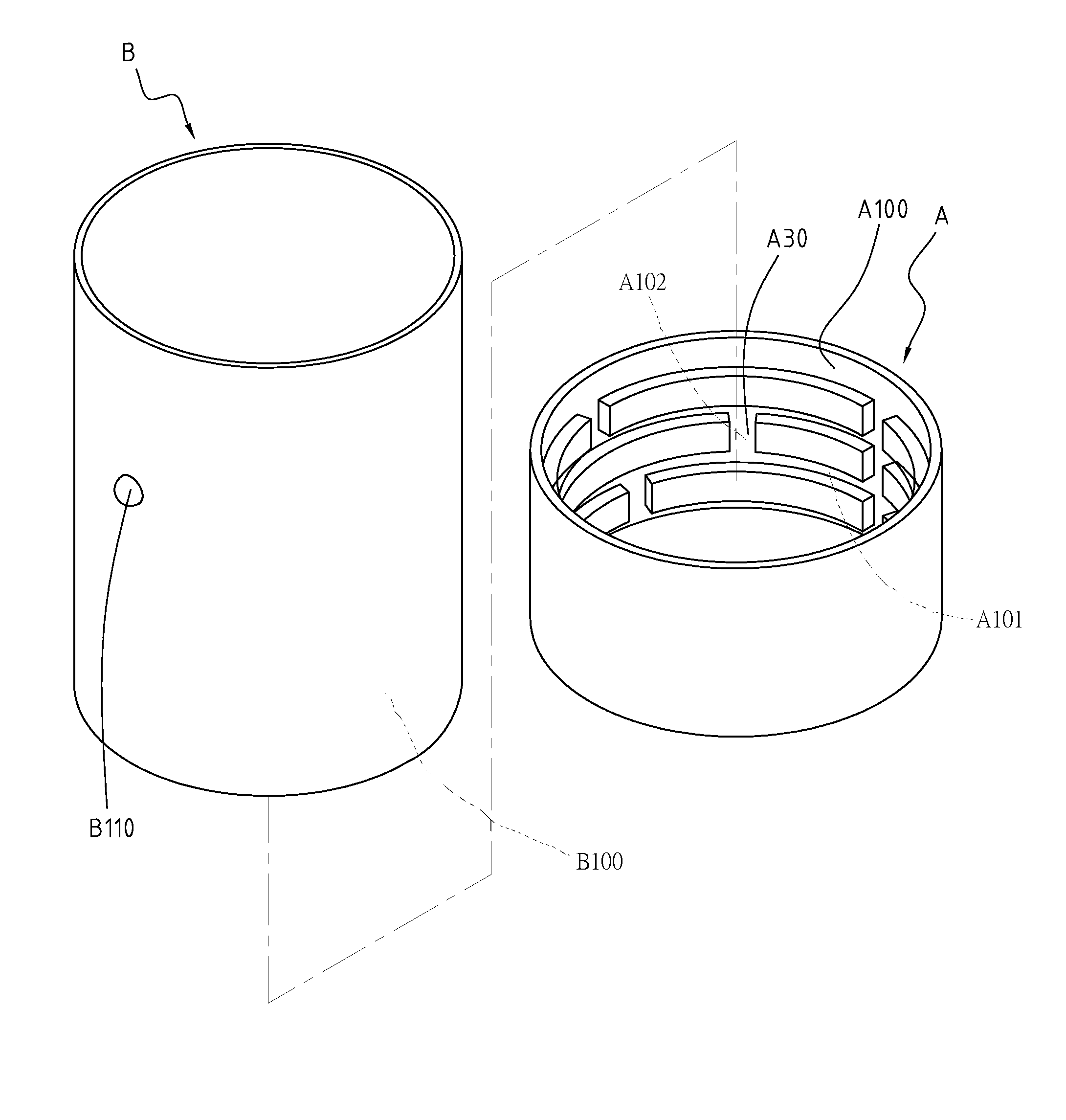
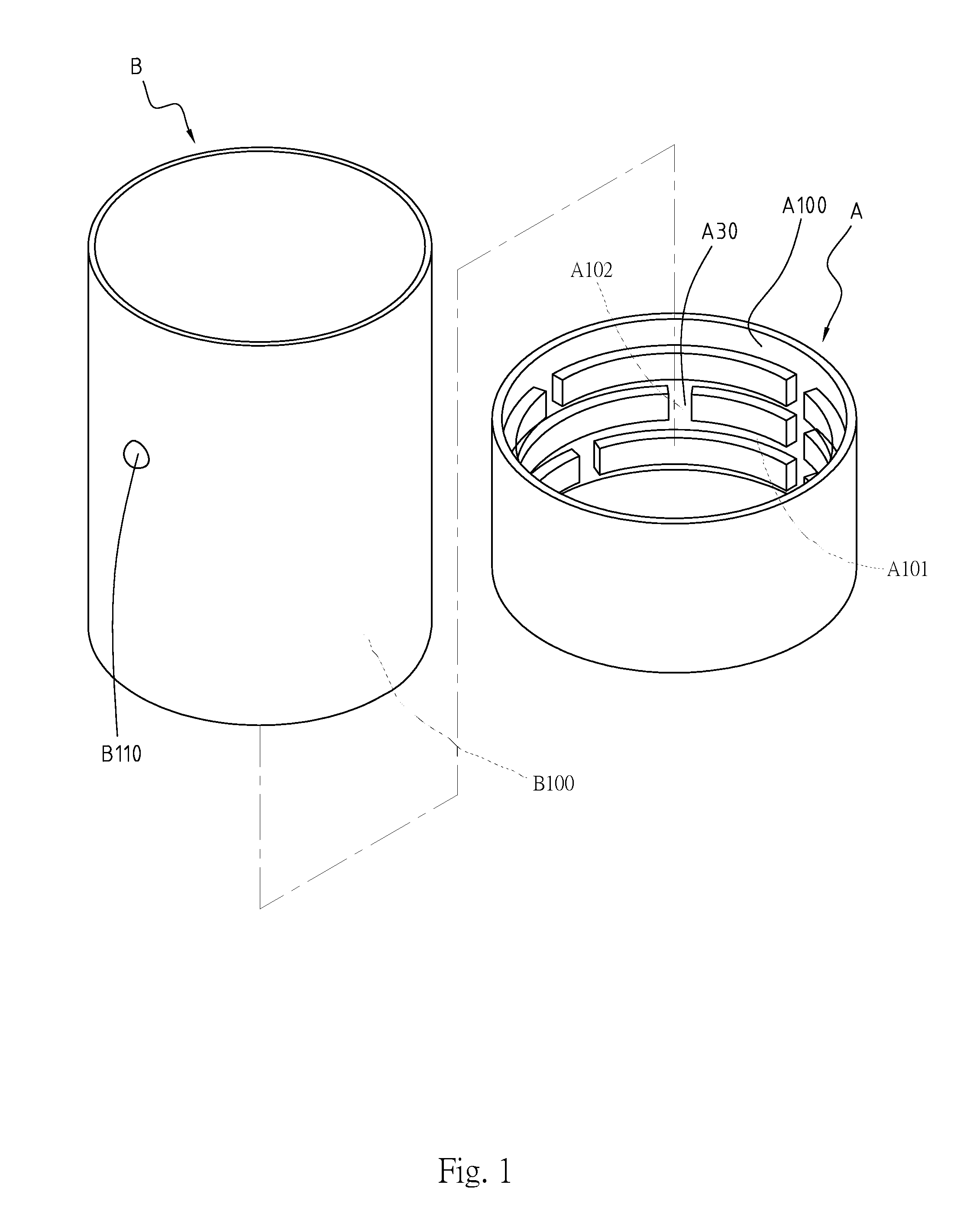
[0033]Please refer to FIG. 1, which shows a structure of intermating members for the instant disclosure. The structure comprises a base B and an annular member A. The base B is essentially a cup-like structure, while the annular member A is a cup sleeve provided for thermal insulation. The base B is shaped annularly, and has a protrusion B110 formed on an outer surface B100 thereof. The outer surface B100 of the base B is fitted with the annular member A. The annular member A has an inner surface A100 in adjacent with the protrusion B110. The inner surface A100 defines a plurality of first grooves A101 and a plurality of second grooves A102. Each of the second grooves A102 is in communication with a pair of adjacent first grooves A101 in defining a sliding path A30. When the user twists the annular member A or moves it generally in an up-and-down direction, the protrusion B110 will traverse the sliding path A30. For the instant disclosure, the base B may be a barrel-shaped holder fo...
second embodiment
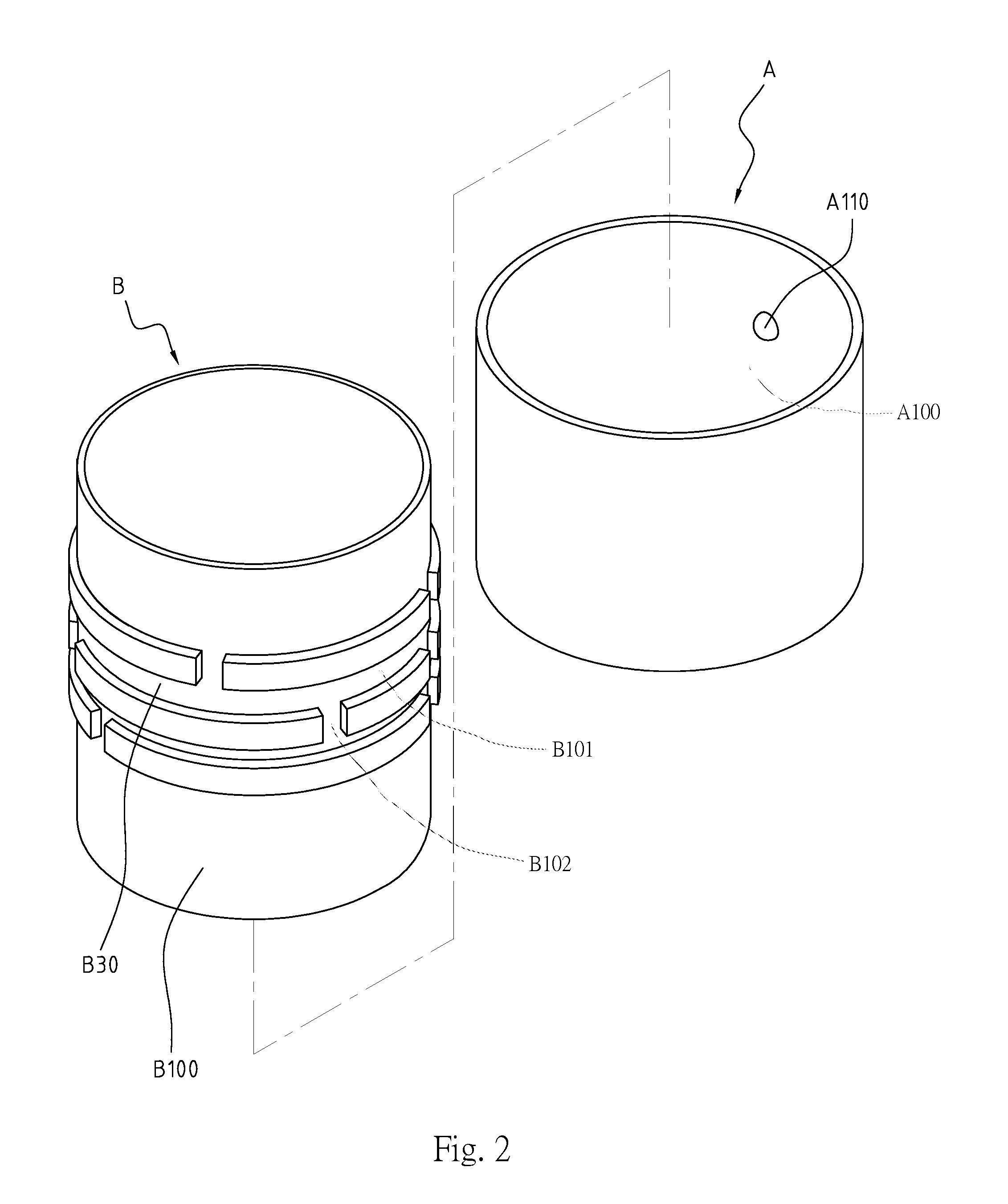
[0034]Please refer to FIG. 2, which shows the structure of intermating members for the instant disclosure. In comparison with the preceding embodiment, a sliding path B30 and a protrusion A110 are formed such that the positions are reversed. That is, the protrusion A110 is formed on the inner surface A100 of the annular member A, while the outer surface B100 of the base B defines a plurality of first and second grooves B101 and B102. Each of the second grooves B102 communicates with at least two first grooves B101 to define the sliding path B30. When the outer surface B100 of the base B is fitted with the annular member A, the protrusion A110 may traverse in the sliding path B30.
[0035]Please refer now to FIG. 3, which shows the structure of intermating members for a third embodiment of the instant disclosure. In this embodiment, the base B is a pencil, and the annular member A is a pencil sleeve. At least a portion of the outer surface of the base B is annularly shaped, and the prot...
fifth embodiment
[0036]Please refer to FIG. 5, which shows the instant disclosure. In this embodiment, the base B is substantially a bottle-like artifact, while the annular member A is substantially a cap. More specifically, the base B has a body portion B01 and a rimmed mouth portion B11. The mouth portion B11 is defined by a sidewall B10 annularly shaped, and the protrusion B110 is formed on the sidewall B10 near the mouth portion B11. The sidewall B10 bridges the body portion B01 and the mouth portion B11. With respect to the body portion B01, the mouth portion B11 is arranged away from one end thereof. It should be understood that the base B may be a PET (polyethylene terephthalate), bottle, a sports bottle, or other container having an opening. The size of the base B and the material(s) for making it are not restricted.
[0037]Please refer again to FIG. 5, in which the annular member A caps off the mouth portion B11. The annular member A has an annular wall portion A10 and a lid portion A11, with...
PUM
 Abstract
Description
Claims
Application Information
 - R&D
- Intellectual Property
- Life Sciences
- Materials
- Tech Scout
- Unparalleled Data Quality
- Higher Quality Content
- 60% Fewer Hallucinations
Browse by: Latest US Patents, China's latest patents, Technical Efficacy Thesaurus, Application Domain, Technology Topic, Popular Technical Reports.
© 2025 PatSnap. All rights reserved.Legal|Privacy policy|Modern Slavery Act Transparency Statement|Sitemap|About US| Contact US: help@patsnap.com


