
Building Entity Relationship Networks from n-ary Relative Neighborhood Trees

a technology of relative neighborhood trees and entity relationships, applied in the field of building entity relationship networks from nary relative neighborhood trees, can solve the problems of not being able to comprehend mathematically optimal diagrams, unable to present regularized structures that make the network visually graspable for human comprehension, and becoming nearly impossible for domain experts to comprehend

Inactive Publication Date: 2015-11-12
IBM CORP
View PDF4 Cites 17 Cited by
  • Summary
  • Abstract
  • Description
  • Claims
  • Application Information

AI Technical Summary

Benefits of technology

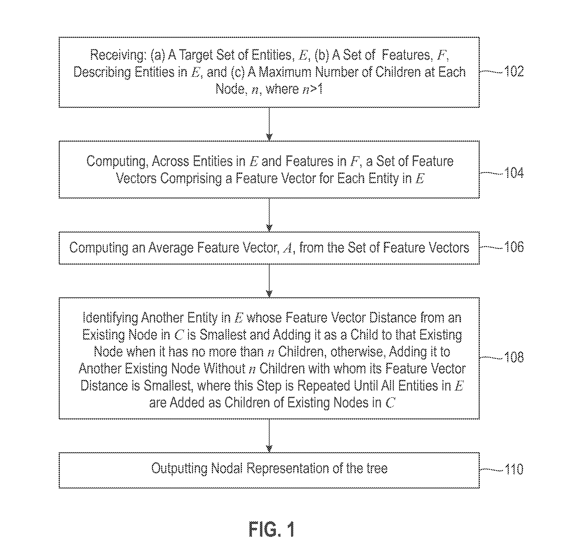
The present invention provides a method for creating a n-ary entity relationship tree that is intuitive to grasp visually at both the broad and detailed level. The method involves receiving a target set of entities, features describing those entities, and a maximum number of allowed children, computing feature vectors for each entity, identifying a root entity with the smallest feature vector distance from the average feature vector, adding other entities to the tree as children if they meet certain criteria, and outputting a nodal representation of the tree. This invention can be implemented using computer-implemented methods and computer-accessible memory media.

Problems solved by technology

The ability to summarize and visualize a complex ontology is a well-known and long studied problem.
But these networks, as they become larger, become nearly impossible for the domain expert to comprehend due to the complexity of the possible interconnections.
Unfortunately, this mathematically optimal diagram may present no regularized structures that make the network visually graspable for human comprehension.
None of these approaches make use of the position in network as an indicator of generality and, further, such representations also typically become harder to understand the larger they grow.

Method used


Image

  • Building Entity Relationship Networks from n-ary Relative Neighborhood Trees
  • Building Entity Relationship Networks from n-ary Relative Neighborhood Trees
  • Building Entity Relationship Networks from n-ary Relative Neighborhood Trees

Examples


example

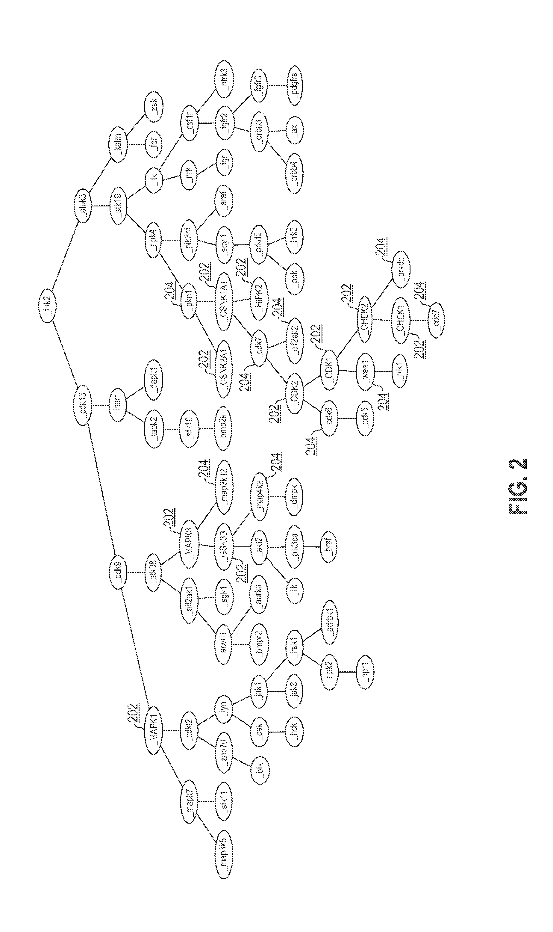
[0040]One example of creating a binary relative neighborhood network was done around P53 kinases. The methodology used created a model of each protein kinase that is based on the Medline® abstracts that contain only that kinase and no others. The feature space of this model is the words and phrases contained in those abstracts. The distance metric is then the cosine similarity (i.e., calculation of angle between the lines that connect each point to the origin) between each kinase's centroid (average of all feature vectors for all abstracts containing the kinase). This distance matrix can then form a similarity graph which can be visualized and reasoned over to identify suspect p53 kinases. These can then be confirmed through experimentation. This method predicted that kinases not previously known to target p53 might indeed do so.

[0041]The kinase network diagram generated according to the teachings of the present invention is depicted in FIG. 2. In FIG. 2, a plurality of nodes labele...


PUM


Abstract

Entities are objects with feature values that can be thought of as vectors in N-space, where N is the number of features. Similarity between any two entities can be calculated as a distance between the two entity vectors. A similarity network can be drawn between a set of entities based on connecting two entities that are relatively near to each other in N-space. Binary relative neighborhood trees are a special type of entity relationship network, designed to be useful in visualizing the entity space. They have the intuitively simple property that the more typical entities occur at the top of the tree and the more unusual entities occur at the leaf nodes. By limiting the number of links to n+1 per node (one parent, n children), a regularized flat tree structure is created that is much easier to visualize and navigate at both a course and a fine level by domain experts.

Description

BACKGROUND OF THE INVENTION[0001]1. Field of Invention[0002]The present invention relates generally to systems and methods for building entity relationship networks. More specifically, the present invention is related to a system, method and article of manufacture for building entity relationship networks from n-ary relative neighborhood trees.[0003]2. Discussion of Related Art[0004]The ability to summarize and visualize a complex ontology is a well-known and long studied problem. The current best approach to solving this problem is based on creating entity similarity networks. But these networks, as they become larger, become nearly impossible for the domain expert to comprehend due to the complexity of the possible interconnections. The assumption is that the best connection to draw between entities is always the mathematically optimal one (e.g., the shortest distance between two points is a straight line). Unfortunately, this mathematically optimal diagram may present no regulari...

Claims


Application Information

Patent Timeline
Patent Type & Authority Applications(United States)
IPC IPC(8): G06F17/30
CPCG06F17/30964G06F17/30958G06F16/2237G06F16/9024G06F16/903G16B40/30
Inventor SPANGLER, W SCOTT
Owner IBM CORP
Learn More