
Air purification apparatus

a technology of air purification apparatus and air purification chamber, which is applied in the field of air purification equipment, can solve the problems that the air purification apparatus cannot produce clean air, and is used to purify indoor air

Inactive Publication Date: 2015-10-22
KONINKLIJKE PHILIPS ELECTRONICS NV
View PDF10 Cites 15 Cited by
  • Summary
  • Abstract
  • Description
  • Claims
  • Application Information

AI Technical Summary

Benefits of technology

The patent is for an air purification apparatus that can be used to bring outdoor air into indoor spaces. The apparatus can choose between using outdoor or indoor air as its source, based on the air quality. An invention feature is the use of a groove on the inner wall of the inlet chamber, which helps to reduce the resistance of the air pumping unit. Additionally, a filter screen covering the groove can provide an air channel for improved ventilation. The apparatus also includes an outlet chamber with a noise reducer to reduce noise when air is pumped through the chamber. The air pumping unit is located between the inlet and outlet chambers, making it easy and inexpensive to implement. Overall, the invention provides a more efficient and effective air purification solution for indoor air quality control.

Problems solved by technology

However, the conventional air purification apparatuses are generally disposed in indoor spaces, and therefore they can only be used to purify indoor air.
When the indoor air quality is poor, such air purification apparatus cannot produce clean air as required because the filtration capability of the filtration component is limited.

Method used


Image

  • Air purification apparatus
  • Air purification apparatus
  • Air purification apparatus

Examples


Embodiment Construction

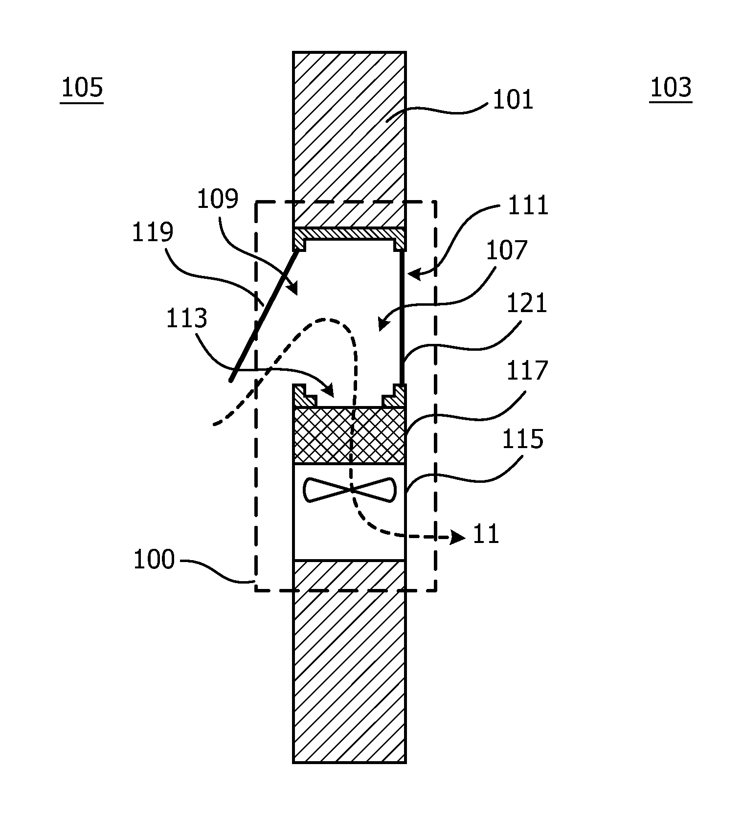
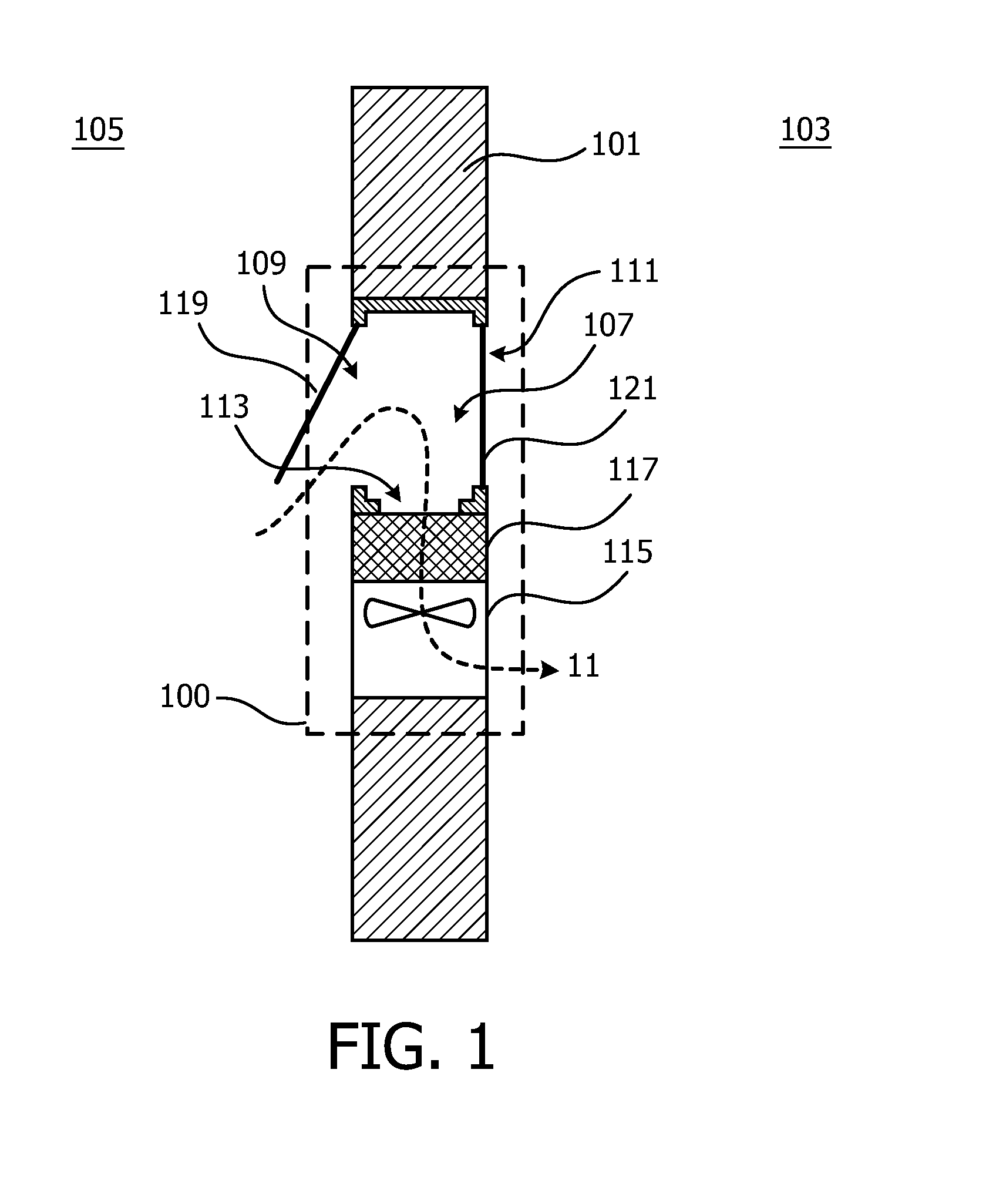
[0022]FIGS. 1 and 2 depict an air purification apparatus 100 according to an embodiment of the invention. The air purification apparatus 100 is used to remove pollutants in air, such as solid particles or organic pollutants (e.g. formaldehyde, toluene or other highly volatile hydrocarbons), and to produce clean air for people. In the embodiment, the air purification apparatus 100 is disposed in a window 101 for separating an indoor space 103 and an outdoor space 105.

[0023]As depicted in FIGS. 1 and 2, the air purification apparatus 100 comprises:[0024]an inlet chamber 107 having a first inlet 109, a second inlet 111 and an outlet 113, wherein the first inlet 109 is operatively open to the outdoor space 105 and the second inlet 111 is operatively open to the indoor space 103;[0025]an air pumping unit 115 for pumping air from the inlet chamber 107 to the indoor space 103 through the outlet 113, wherein the air is pumped into the inlet chamber 107 through the first inlet 109 or through...


PUM

PropertyMeasurementUnit
temperatureaaaaaaaaaa
flow resistanceaaaaaaaaaa
corrosionaaaaaaaaaa

Abstract

The invention relates to an air purification apparatus. The apparatus is disposed in a window for separating an indoor space and an outdoor space. The apparatus comprising: an inlet chamber having a first inlet, a second inlet and an outlet, wherein the first inlet is operatively open to the outdoor space and the second inlet is operatively open to the indoor space; an air pumping unit for pumping air from the inlet chamber to the indoor space through the outlet, wherein the air is pumped into the inlet chamber through the first inlet or through the second inlet; and a filtering unit disposed upstream of the air pumping unit, for filtering pollutants in the air.

Description

FIELD OF THE INVENTION[0001]The invention generally relates to air purification technology, and more particularly relates to an air purification apparatus.BACKGROUND OF THE INVENTION[0002]Air purification apparatuses have been widely used in many circumstances, such as offices, workshops or medical facilities, for removing pollutants in air and providing purified air to people. The air purification apparatuses typically comprise a filtration component, which collects the pollutants, such as solid particles or organic pollutants, when air flows therethrough. However, the conventional air purification apparatuses are generally disposed in indoor spaces, and therefore they can only be used to purify indoor air. When the indoor air quality is poor, such air purification apparatus cannot produce clean air as required because the filtration capability of the filtration component is limited.SUMMARY OF THE INVENTION[0003]It would be, therefore, advantageous to provide an air purification ap...

Claims


Application Information

Patent Timeline
Patent Type & Authority Applications(United States)
IPC IPC(8): F24F11/053E06B7/02F24F7/013F24F3/16B01D46/42B01D46/44F24F8/108F24F8/158F24F11/76
CPCF24F11/053B01D46/4236B01D46/448F24F2003/1614F24F3/1603E06B7/02F24F7/013F24F11/0001F24F2221/20E06B2007/023F24F11/30F24F2110/10F24F11/76F24F8/108F24F11/56F24F11/65F24F8/158F24F8/80Y02A50/20
Inventor WANG, WEIRAN
Owner KONINKLIJKE PHILIPS ELECTRONICS NV
Learn More