Autoinjector

a technology of auto-injector and injection needle, which is applied in the direction of intravenous devices, infusion needles, other medical devices, etc., can solve the problems of inability to the injection will stop and may not deliver the intended dose, and the force required to push the button/plunger may be too high

Active Publication Date: 2015-10-22
SANOFI AVENTIS DEUT GMBH
View PDF4 Cites 19 Cited by
  • Summary
  • Abstract
  • Description
  • Claims
  • Application Information

AI Technical Summary

Benefits of technology

The present invention provides an improved autoinjector with a case, a door, a plunger, and a drive spring. The door is hingedly connected to the case and can be opened and closed. The plunger is slidably disposed in the case and can be moved from a distal position to a proximal position and compress the drive spring when the door is opened. The autoinjector also includes an interlock sleeve, an interlock beam, and a retractable needle boot. The interlock sleeve has an aperture that engages a needle boot when the door is opened. The invention also includes a trigger button, a piston rod, and a roller. The pharmaceutically active compound can be insulin or a peptide for the treatment of diabetes mellitus or complications associated with diabetes mellitus.

Problems solved by technology

Administering an injection is a process which presents a number of risks and challenges for users and healthcare professionals, both mental and physical.
There are numerous disadvantages associated with this approach.
For example, if the button / plunger is released prematurely, the injection will stop and may not deliver an intended dose.
Further, the force required to push the button / plunger may be too high (e.g., if the user is elderly or a child).
Conventional electro-mechanical or fully electronic autoinjectors may not be as robust as fully mechanical autoinjectors.
For example, electro-mechanical or fully electronic autoinjectors may include batteries which require replacement and may be more difficult or impossible to fix if a component breaks.

Method used


Image

  • Autoinjector
  • Autoinjector
  • Autoinjector

Examples


Embodiment Construction

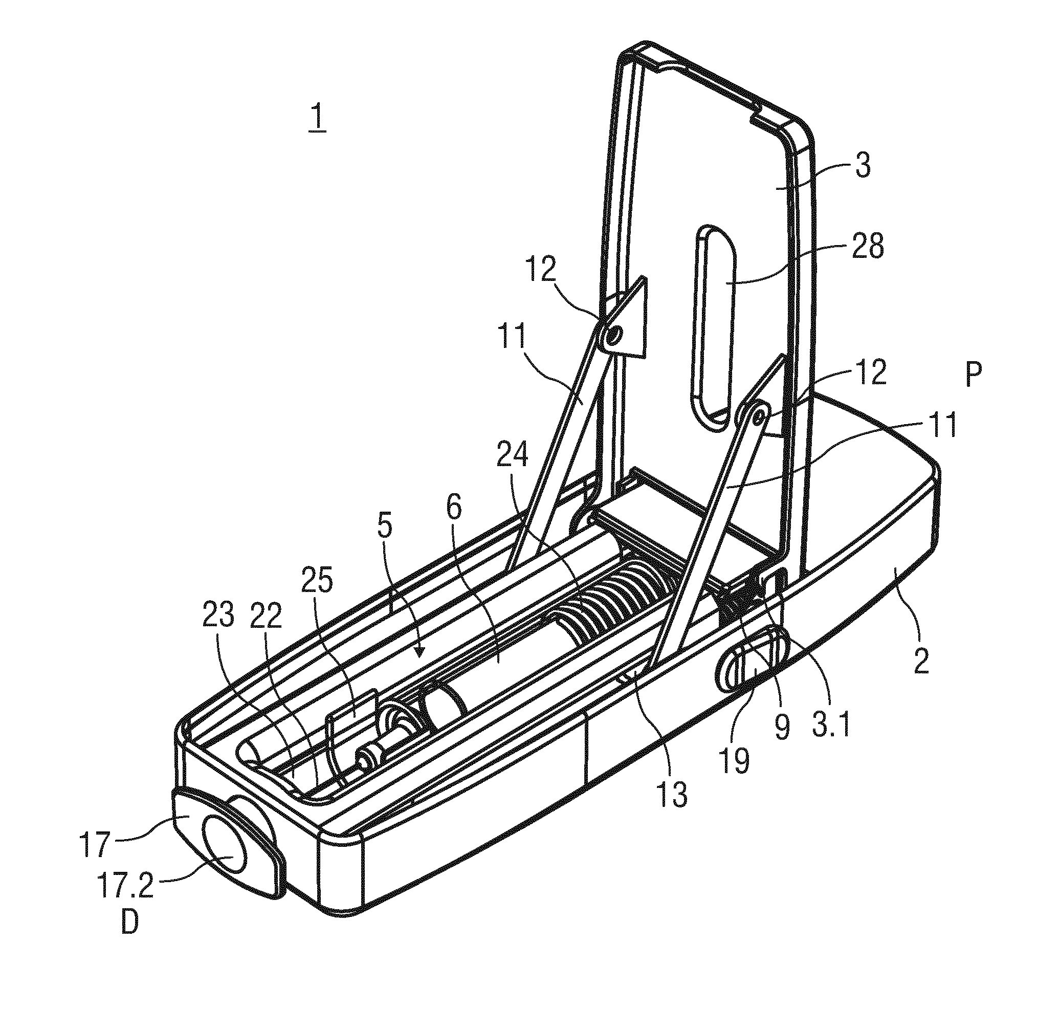
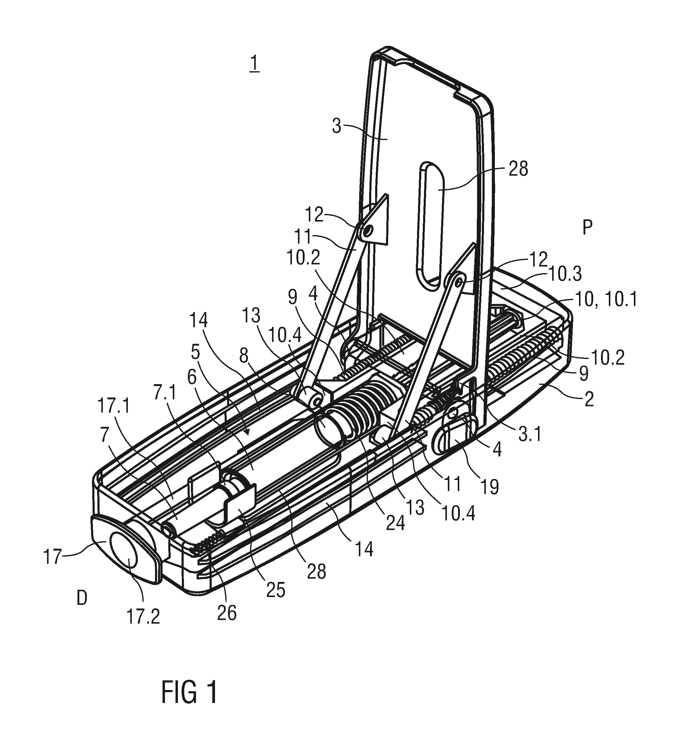
[0107]FIG. 1 is a perspective semitransparent view of an exemplary embodiment of an autoinjector 1 according to the present invention.

[0108]In an exemplary embodiment, the autoinjector 1 comprises a case 2 designed to be held by a patient, health-care provider or other user during an injection. The case 2 may have a generally elongate, rectangular shape and may include one or more ergonomic features (e.g., finger grooves for gripping) and / or textured surfaces or skins for preventing a user's hand from slipping while using the autoinjector 1.

[0109]In an exemplary embodiment, the case 2 includes a door 3 which is configurable in an open position or a closed position. In the open position, the door 3 provides access to a syringe carrier in the case 2 that is adapted to hold a syringe 6 or a cartridge containing a medicament. In the closed position, the door 3 may be locked. As shown in the exemplary embodiment in FIG. 1, the door 3 may be formed on a side of the case 2 and rotate about...


PUM


Abstract

Described is an autoinjector comprising a case, a door hingedly coupled to the case and having an open position and a closed position, a plunger slidably disposed in the case, and at least one drive spring applying a biasing force on the plunger relative to the case, wherein the door is operably coupled to the plunger, and wherein rotation of the door from the closed position to the open position moves the plunger from a distal position in the case to a proximal position in the case and compresses the at least one drive spring.

Description

TECHNICAL FIELD[0001]The invention relates to an autoinjector for administering a medicament.BACKGROUND OF THE INVENTION[0002]Administering an injection is a process which presents a number of risks and challenges for users and healthcare professionals, both mental and physical. Injection devices typically fall into two categories—manual devices and autoinjectors. In a conventional manual device, manual force is required to drive a medicament through a needle. This is typically done by some form of button / plunger that has to be continuously pressed during the injection. There are numerous disadvantages associated with this approach. For example, if the button / plunger is released prematurely, the injection will stop and may not deliver an intended dose. Further, the force required to push the button / plunger may be too high (e.g., if the user is elderly or a child). And, aligning the injection device, administering the injection and keeping the injection device still during the inject...

Claims


Application Information

Patent Timeline
IPC IPC(8): A61M5/20A61M5/32A61M5/31
CPCA61M5/2033A61M5/3129A61M5/3245A61M2005/202A61M5/326A61M2005/208A61M2005/314A61M2005/3247A61M2205/586A61M2005/206A61M5/3204A61M5/3202A61M5/46A61M2205/581A61M2205/582A61M2205/583A61M2205/60A61M2205/6009A61M2205/3368
Inventor HENDERSON, CHARLEYCROSS, DAVIDJENNINGS, DOUGLAS IVANMCGINLEY, RYAN ANTHONY
Owner SANOFI AVENTIS DEUT GMBH
Why Eureka
Try Eureka